131
7 Construction of bodies
7.2 Mounting frame
MITSUBISHI FUSO body/equipment mounting directives for FE Issue date: 20. 10. 2020
! Only print out complete sections from the current version
• Carry out the following in order to prevent stress
concentrating at the front end of the mounting
frame. Make the length of the tapered part of the
bottom end of the mounting frame between 100
and 200 mm, and end the taper at a point that is
not past (A). If a taper cannot be secured, form the
end to a radius of at least 10, and extend the end
part to the front (vicinity of the shackle).
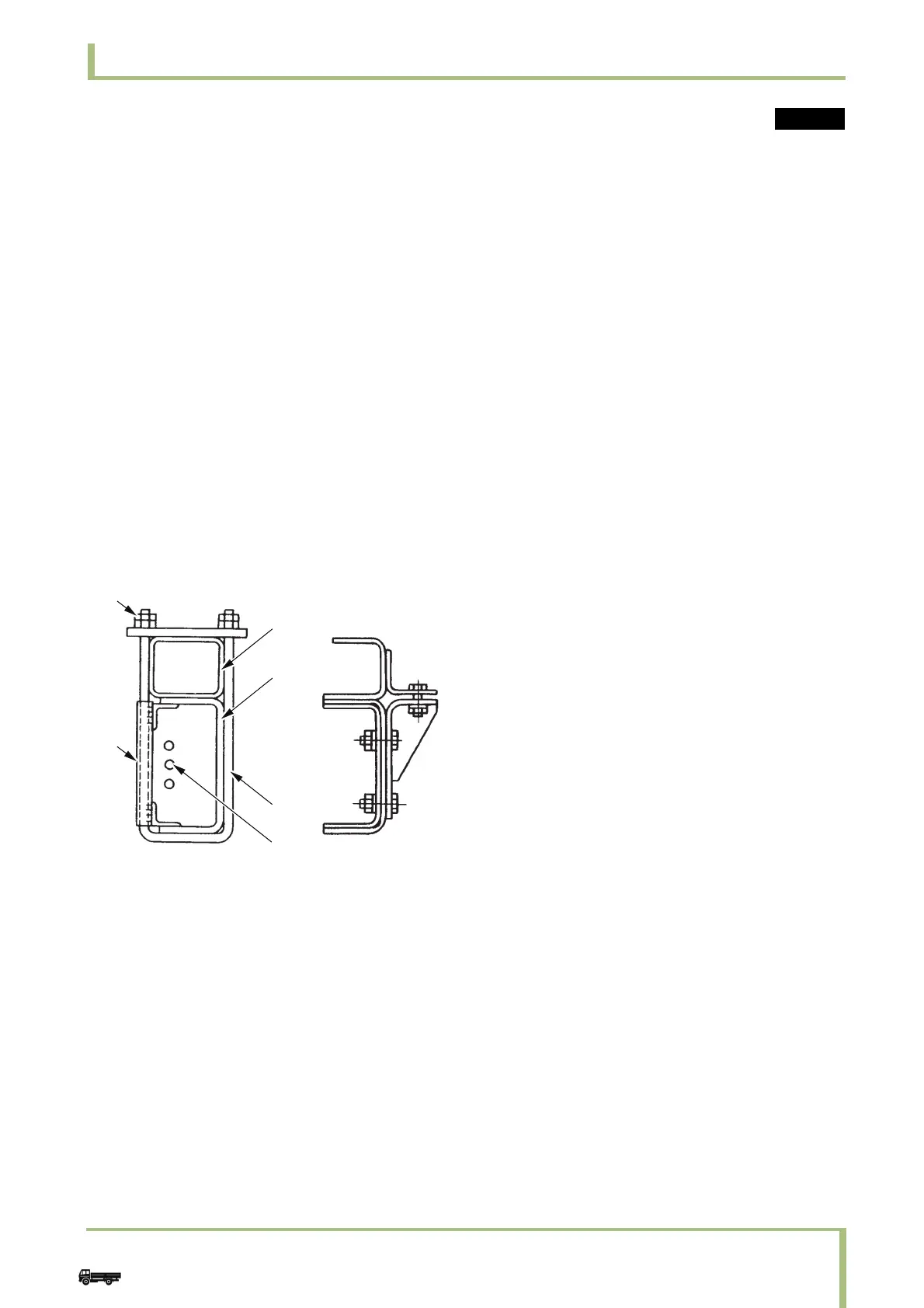
• To connect the mounting frame to the chassis
frame, either use U-bolts, or in the case of a heavy
body building part fix the mounting frame with
opposing brackets and ensure that the load
imposed by the body building part plus the freight
is borne by both the mounting frame and the
chassis frame.
Ensure that the front end connecting part is
frontward of the No.2 cross member (transmission
suspension part). A large number of hoses and
wires pass through this area, so take care not to
damage them when installing the U-bolts.
1Use double nuts
2Mounting frame
3 Chassis frame
4U-bolt
5 Pipings
6 Misalignment stopper
Cargo



 To Next Page