JF-240UV User Manual
133
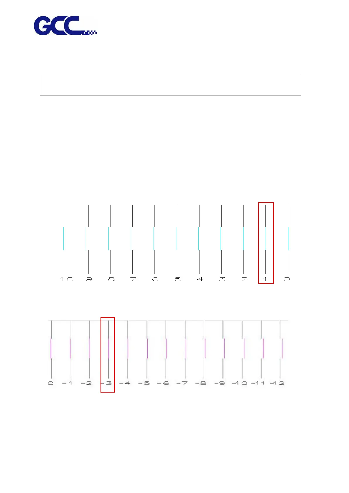
Following are horizontal alignment calibration examples (please refer to Example 1 and Example
2):
Note: Please read the following information thoroughly prior you proceed to the inkjet head
horizontal alignment calibration.
6. Please use K (black) color to calibrate other colors.
7. There are 31 calibration lines on the horizontal calibration pattern chart. Numbers are layout from left to
right. Please refer to Figure 4-70, the 16
th
P line (0) is the initial number.
8. These numbers will indicate the offset (bias) value for each inkjet head
Example 1: Horizontal alignment calibration for the inkjet head of Cyan color.
Example 2: Horizontal alignment calibration for the inkjet head of Magenta color
Step 1. Enlarge the Cyan calibration test pattern chart to Example 1. Use a magnify lens to
observe that Cyan line and Black line are aligned at number “1” line. Keep a record on the
number where two lines are aligned.