JF-240UV User Manual
137
Step 1. Enlarge the Cyan calibration test pattern chart to Example 1. Use a magnify lens to
observe that Cyan line and Black line are aligned at number “1” line. Keep a record on the
number where two lines are aligned.
Step 2. Use a magnify lens to observe that Magenta line and the Black line are aligned at number
“-3” line (as Example 2), please keep a record on the number where two lines are aligned.
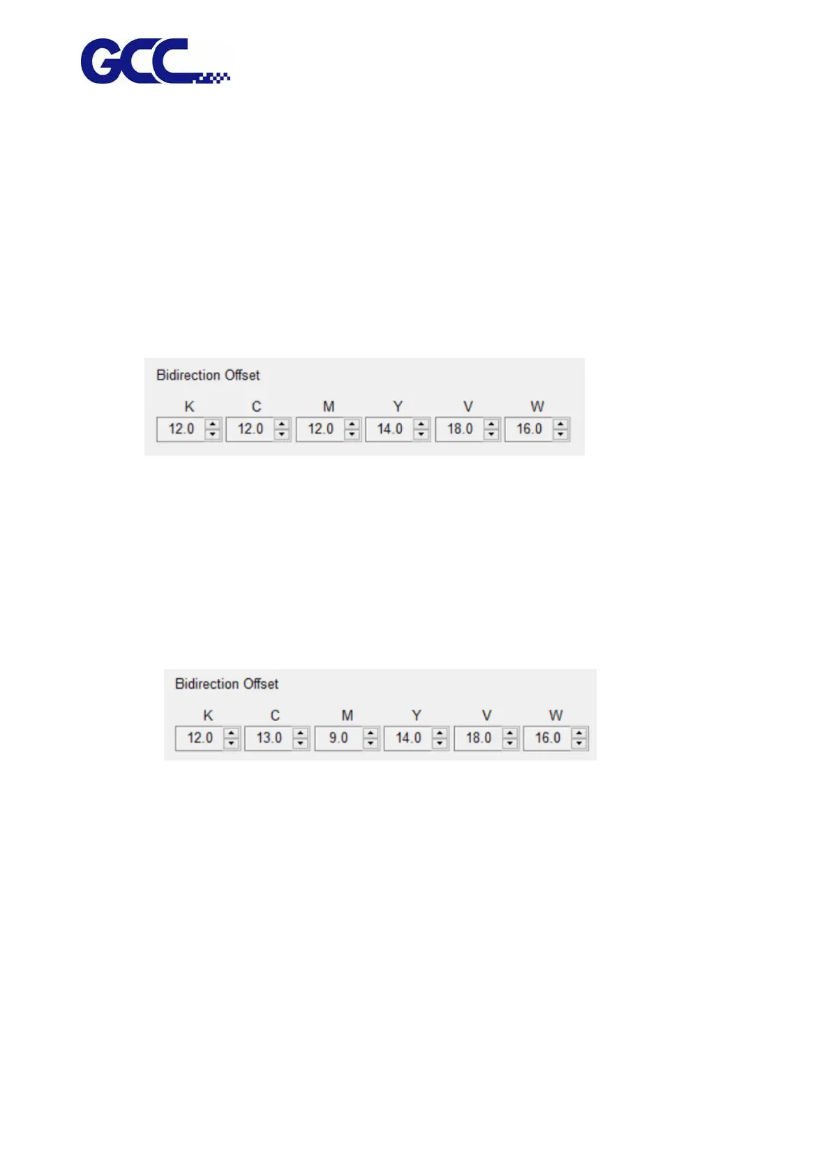
Step 3. After record all the offsets for all the colors, go to the control interface of “Bidirection
Offset 「K、C、M、Y、W、V」” for JF-240UV VCLD software to conduct bidirectional
calibration.
In the Example 1: Cyan line shift 1 line to the left indicates that the bidirectional offset for the color
Cyan need to be increased 1. In the Example 2 : Magenta line shift 3 line to the right stands for that
the horizontal offset for the color Magenta need to be decreased 3.
For example: M=12-3=9 (Enter 9 in JF-240UV (VLCD)
C=12+1=13 (Enter 13 in JF-240UV (VLCD)
Step 4. Use the same approach to calibrate other inkjet heads.
Step 5. Use this method to enter the offset values for all the inkjet heads, then press Save to
update the settings.