CGCOMMUNICATIONS GUIDE PROFIBUS-DPV1 COMMUNICATIONS
369 MOTOR MANAGEMENT RELAY – COMMUNICATIONS GUIDE CG19
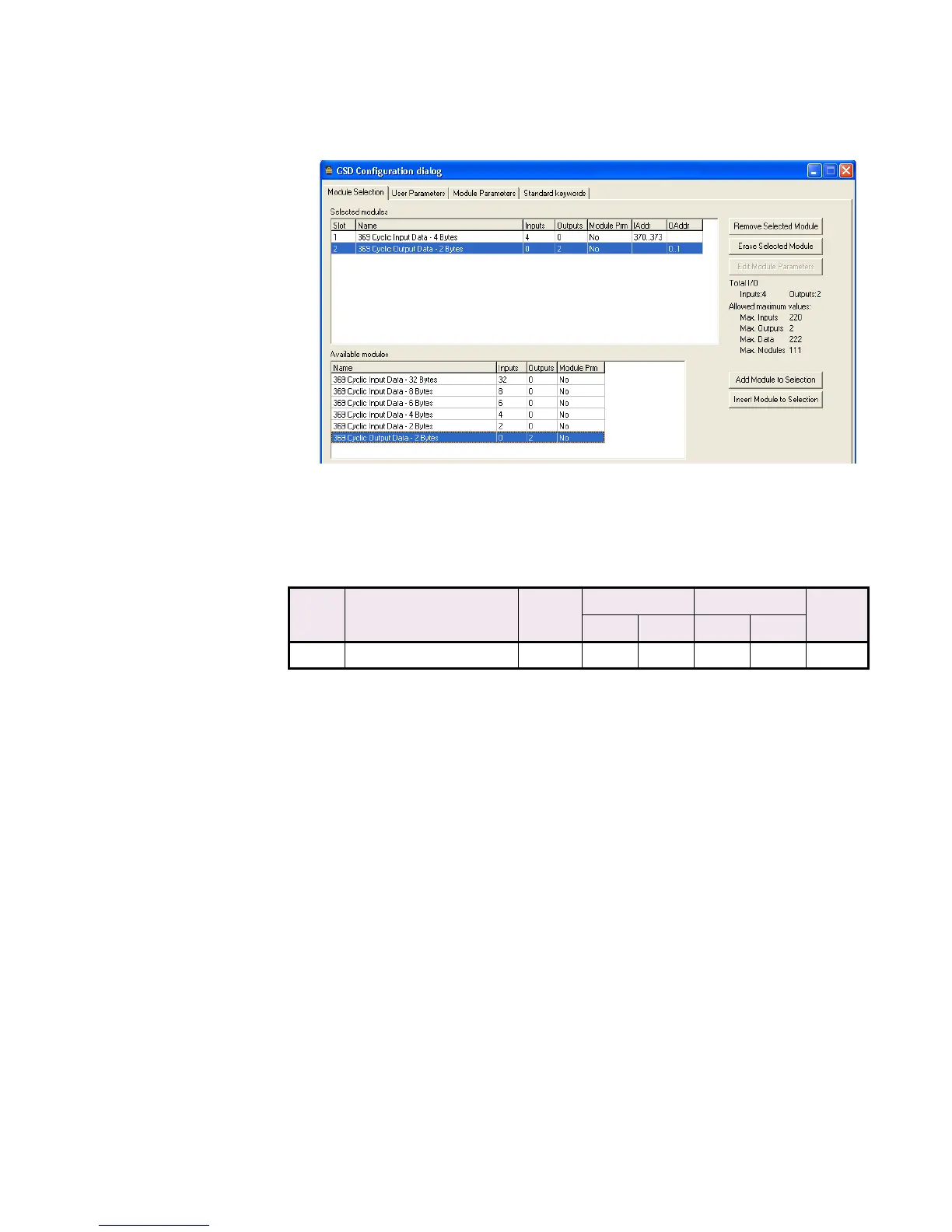
A slave configuration example for 4 bytes of input data and 2 bytes of output data is
shown below.
FIGURE CG–5: Slave Configuration Example – 4 Bytes of Input Data, 2 bytes of Output Data
3.5 369 Relay Profibus Diagnostics
The diagnostic data available for the Profibus-DPV1 option matches Table CG–3: Profibus
Diagnostics on page CG–9. When no diagnostic information is available and the master
initiates a diagnostics read, the six slave mandatory bytes are read.
3.6 369 Relay Profibus-DPV1 Acyclical Communication
The following items have been made available through Profibus-DPV1 acyclical
communication. Data is addressed through the use of “slot and index” addressing. Three
parameters are required to read or write data from the 369 Relay using a Profibus-DPV1
master:
1. Slot number
2. Index number
3. Data length (number of 16-bit words)
Table CG–4: Profibus Output Data
OFFSET CYCLIC DATA
(ACTUAL VALUES)
LENGTH
(BYTES)
MINIMUM MAXIMUM FORMAT
CODE
VALUE HEX VALUE HEX
0Force Output Relays 2 0015FF141