CG38 369 MOTOR MANAGEMENT RELAY – COMMUNICATIONS GUIDE
MODBUS RTU PROTOCOL CGCOMMUNICATIONS GUIDE
5 Modbus RTU Protocol
5.1 Data Frame Format and Data Rate
One data frame of an asynchronous transmission to or from an 369 is default to 1 start bit,
8 data bits, and 1 stop bit. This produces a 10 bit data frame. This is important for
transmission through modems at high bit rates (11 bit data frames are not supported by
Hayes modems at bit rates of greater than 300 bps). The parity bit is optional as odd or
even. If it is programmed as odd or even, the data frame consists of 1 start bit, 8 data bits,
1 parity bit, and 1 stop bit.
Modbus protocol can be implemented at any standard communication speed. The 369
RS485, fiber optic and RS232 ports support operation at 1200, 2400, 4800, 9600, and
19200 baud.
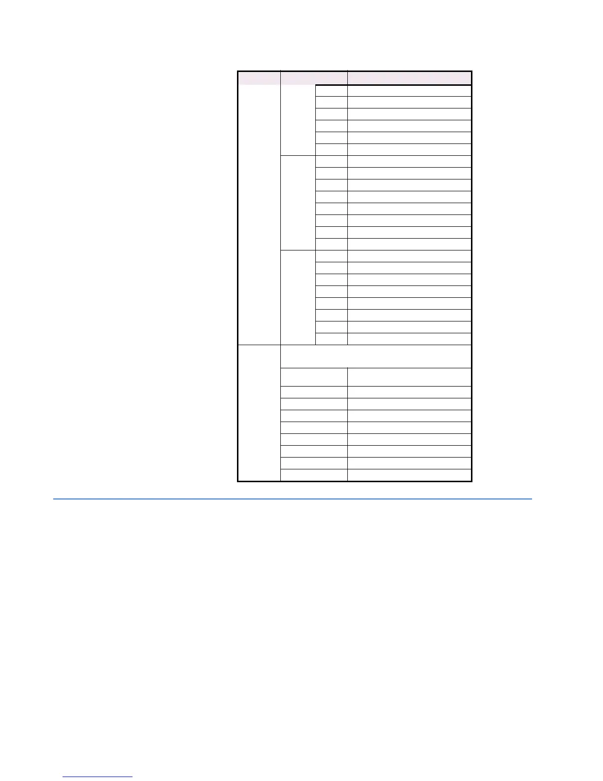
Bit 2 RTD 9 High Alarm
Bit 3 RTD 10 High Alarm
Bit 4 RTD 11 High Alarm
Bit 5 RTD 12 High Alarm
Bit 6 Open RTD Sensor Alarm
Bit 7 Short RTD Alarm
Byte 7 Bit 0 Trip Counters Alarm
Bit 1 Starter Failure Alarm
Bit 2 Current Demand Alarm
Bit 3 kW Demand Alarm
Bit 4 kvar Demand Alarm
Bit 5 kVA Demand Alarm
Bit 6 Digital Counter Alarm
Bit 7 Overload Lockout Block
Byte 8 Bit 0 Start Inhibit Block
Bit 1 Starts Hour Block
Bit 2 Time Between Starts Block
Bit 3 Restart Block
Bit 4 Reserved
Bit 5 Back-Spin Block
Bit 6 Loss of Remote RTD Communication
Bit 7 Spare Switch Alarm
F178 DeviceNet Communication status: unsigned
16 bit integer
Bit 0
0 = not owned,
1 = owned by master
Bit 1 Reserved
Bit 2 0 = factory default, 1= configured
Bits 3 to 7 Reserved
Bit 8 1 = Minor recoverable fault
Bit 9 1 = Minor unrecoverable fault
Bit 10 1 = Major recoverable fault
Bit 11 1 = Major unrecoverable fault
Bits 12 to 15 Reserved
FORMAT VALUE NAME/DESCRIPTION