GFK-0356Q Chapter 2 Installation 2-15
2
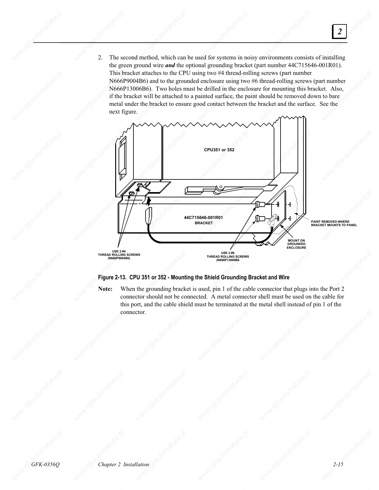
2. The second method, which can be used for systems in noisy environments consists of installing
the green ground wire and the optional grounding bracket (part number 44C715646-001R01).
This bracket attaches to the CPU using two #4 thread-rolling screws (part number
N666P9004B6) and to the grounded enclosure using two #6 thread-rolling screws (part number
N666P13006B6). Two holes must be drilled in the enclosure for mounting this bracket. Also,
if the bracket will be attached to a painted surface, the paint should be removed down to bare
metal under the bracket to ensure good contact between the bracket and the surface. See the
next figure.
MOUNT ON
GROUNDED
ENCLOSURE
USE 2 #6
THREAD ROLLING SCREWS
(N666P13006B6
USE 2 #4
HREAD ROLLING SCREWS
(N666P9004B6)
44C715646-001R01
CPU351 or 352
PAINT REMOVED WHERE
BRACKET MOUNTS TO PANEL
BRACKET
Figure 2-13. CPU 351 or 352 - Mounting the Shield Grounding Bracket and Wire
Note: When the grounding bracket is used, pin 1 of the cable connector that plugs into the Port 2
connector should not be connected. A metal connector shell must be used on the cable for
this port, and the cable shield must be terminated at the metal shell instead of pin 1 of the
connector.

 Loading...


