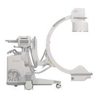
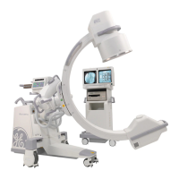
3.3.2. Moving the C-Arm
Familiarize yourself with the location and mechanical operation of all controls prior to moving the C-Arm.
Use the handles provided on the C-Arm to position mechanical assemblies.
1. Return all moving assemblies to their most compact positions. Lower the vertical column and retract
the Cross-Arm. Remove the cassette holder if fitted. (Do this before switching off the mobile C-Arm).
When the C-Arm is positioned on more than or equal to 10° incline, and the mechanical
parts are extended to their greatest length, if the cassette holder is attached, the C-Arm will
be unstable. Please be sure to put the C-Arm in its compact position.
2. Lock all movable mechanical assembly brakes: the C-Arm orbital rotation brake, the lateral rotation
brake, the Wig-Wag brake, and the horizontal Cross-Arm brake.
3. Press and hold the power on/off key 2 seconds on the Workstation to switch the system off. Unplug the
power supply cable and secure the power cable.
4. Disconnect the interconnect cable from the C-Arm and coil and secure the cable around the
Workstation's handles.
5. Disconnect the footswitch and secure it on the C-Arm. Store the handswitch in its holder.
6. Place the C-Arm's steering handle in the normal position and unlock the wheel brakes.
7. Guide the C-Arm by pushing with the steering handles.
Do not move the C-Arm over inclines greater than 10°. Do not move the C-Arm up or down
stairs or steps.
Do not lock the C-Arm in place on an incline greater than 5°.
Transport the system at normal speed. Get across ramps and thresholds as slow as
possible.
8. When you reach your destination, place the C-Arm’s brake pedal in the locked position.

 Loading...


