GE HEALTHCARE
DIRECTION 5245279, REVISION 3 LOGIQ™ P6/P6 PRO SERVICE MANUAL
8 - 64 Section 8-2 - DISASSEMBLY/RE-ASSEMBLY
8-2-25-3 Removal procedure (cont’d)
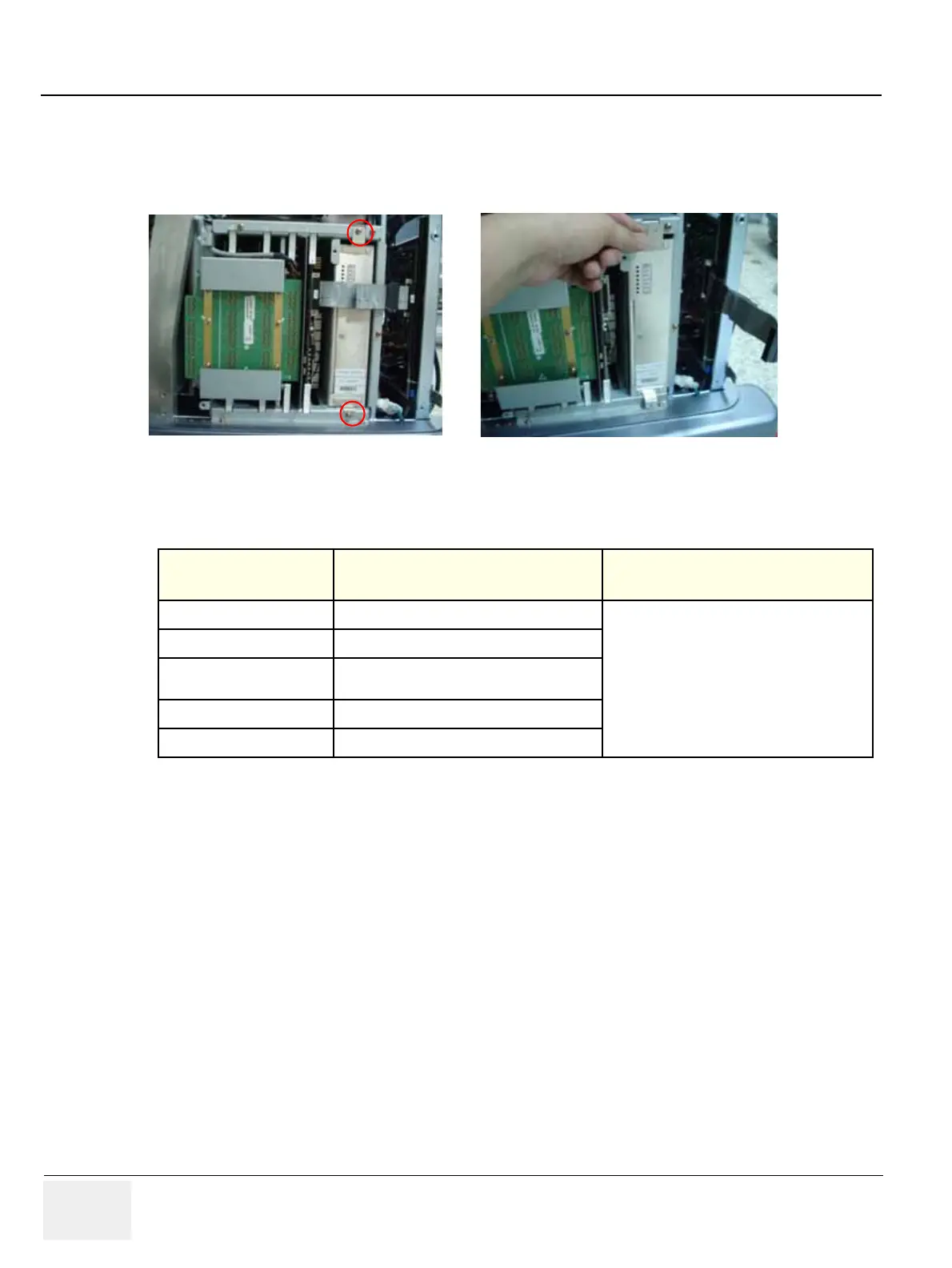
8.) Unplug the J14 connector, and unscrew 2 screws. Pull out the APS II Assy carefully.
Note: AC power input connector should be passed through the square hole on shassis bottom.
Refer to the Figure 8-104.
9.) Perform the following functional tests. If all are successful, include the debrief script provided below.
8-2-25-4 Mounting Procedure
Install the new parts in the reverse order of removal.
Figure 8-104 Pull out the APS Assy
Table 8-26 Functional Tests
Service Manual
Section
Functional Test / Diagnostic Test Debrief Script
Section 4-3-1
Power On/Boot Up
“Service Manual, Direction
5245279, Rev 3+, Section 8-2-25. Equipment
passed all required tests and is ready for use. “
Section 4-3-2
Power Off / Shutdown
Section 4-9-5
APS II Assy PCB Function Validation
Procedure
Section 10-5-2
Functional Checks (See Also Chapter 4)
Section 10-5-5
Physical Inspection

 Loading...


