EasyManuals Logo

GE LOGIQ P6 Service Manual

GE LOGIQ P6
478 pages
To Next Page IconTo Next Page
To Previous Page IconTo Previous Page
Page #285 background imageLoading...
Page #285 background image
GE HEALTHCARE
DIRECTION 5245279, REVISION 3 LOGIQ™ P6/P6 PRO SERVICE MANUAL
Section 8-2 - DISASSEMBLY/RE-ASSEMBLY 8 - 65
8-2-26 DTRX64II Assy
8-2-26-1 Tools
Common philips screwdrivers
8-2-26-2 Preparations
Shut down the system and switch off the main breaker.
8-2-26-3 Removal procedure
1.) Remove the Side Right Cover. Refer to the 8-2-14 "Right or Left Side Cover" on page 8-47.
2.) Remove the EMI Cover R. Refer to the 8-2-24 "EMI Cover L and R" on page 8-62.
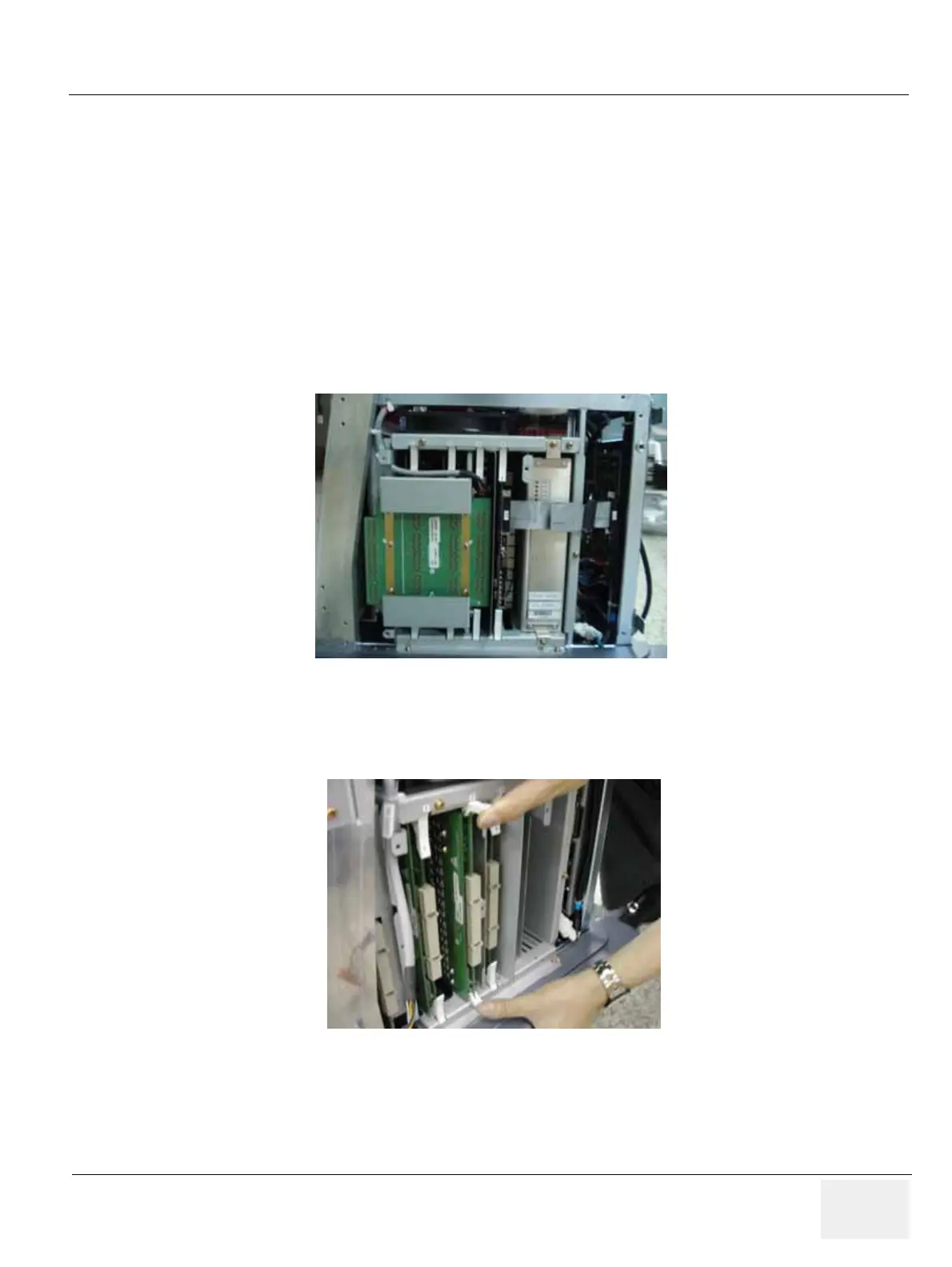
3.) Unscrew 2 screws (1-2) and eject the PCB. Refer to the Figure 8-105.
4.) The DTRX64II Assys are settled in #1 and #2 slots in nest box.
5.) Pull the DTRX64II assy(s) out. Refer to the Figure 8-106.
Figure 8-105 Eject RFC Assy
Figure 8-106 DTRX64II Assy

Table of Contents

Other manuals for GE LOGIQ P6

Questions and Answers:

Question and Answer IconNeed help?

Do you have a question about the GE LOGIQ P6 and is the answer not in the manual?

GE LOGIQ P6 Specifications

General IconGeneral
TypeUltrasound System
ConnectivityDICOM, USB, Ethernet
ApplicationsObstetrics, Gynecology, Vascular, Cardiology, Musculoskeletal
ProbesConvex, Linear, Phased Array
Imaging ModesB-mode, M-Mode, Color Doppler, Power Doppler, Pulsed Wave Doppler
PortabilityMobile
Transducer Ports3 active ports

Related product manuals