GE HEALTHCARE
DIRECTION 5245279, REVISION 3 LOGIQ™ P6/P6 PRO SERVICE MANUAL
Section 8-7 - Mechanical Option Installation instruction 8 - 157
8-7-1-3 Removal procedure (cont’d)
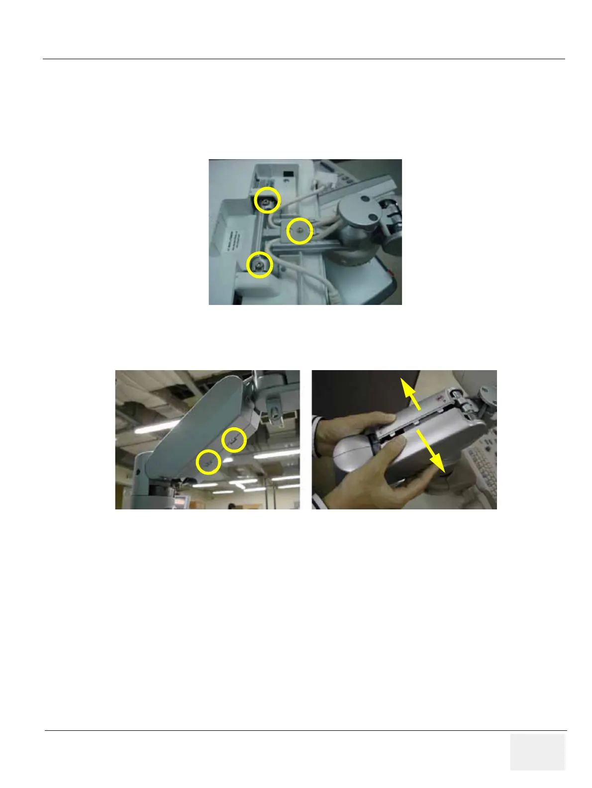
6.) Unscrew 2 screws (5177684, HSH M5x20 WHT) to separate the LCD MONITOR and 1 screw
(2159625, PH M4x8 W/SP) to remove the Cable bracket. Refer to the figure below.
NOTE: While unscrewing the hinge hexa screw from the arm, keep hold of the monitor to prevent
dropping down.
7.) Unscrew 2 screws (2337572, FH M3x6 WHT) to remove the Arm cover L & R. Refer to the figure
below.
Figure 8-236 Separating the LCD monitor & Removing the Cable bracket
Figure 8-237 Removing the Arm cover L & Arm cover R

 Loading...


