GE HEALTHCARE
DIRECTION 5245279, REVISION 3 LOGIQ™ P6/P6 PRO SERVICE MANUAL
8 - 158 Section 8-7 - Mechanical Option Installation instruction
8-7-1-3 Removal procedure (cont’d)
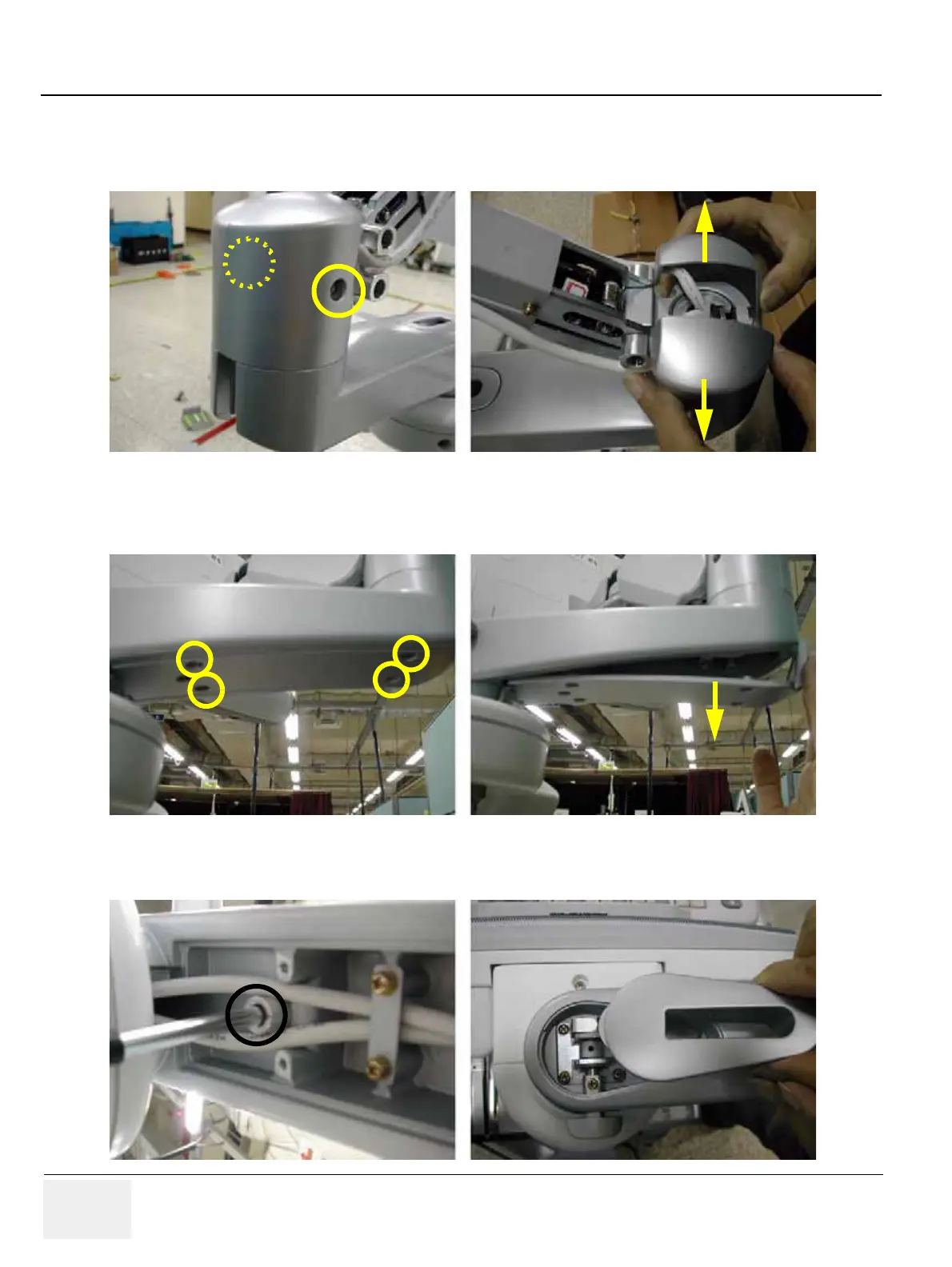
8.) Unscrew 2 screws (2159632, BH M4x6 WHT) to remove the Cam cover L & R. Refer to the figure
below.
9.) Unscrew 4 screws (2159634, BH M4x10 WHT) to remove the Arm bottom cover. Refer to the figure
below.
10.) Unscrew 1 screw (2329677, TAP M4X16) to remove the Lock cover. Refer to the figure below.
Figure 8-238 Removing the Cam cover L & Cam cover R
Figure 8-239 Removing the Arm bottom cover
Figure 8-240 Removing the Lock cover

 Loading...


