GE HEALTHCARE
DIRECTION 5245279, REVISION 3 LOGIQ™ P6/P6 PRO SERVICE MANUAL
Section 8-7 - Mechanical Option Installation instruction 8 - 159
8-7-1-3 Removal procedure (cont’d)
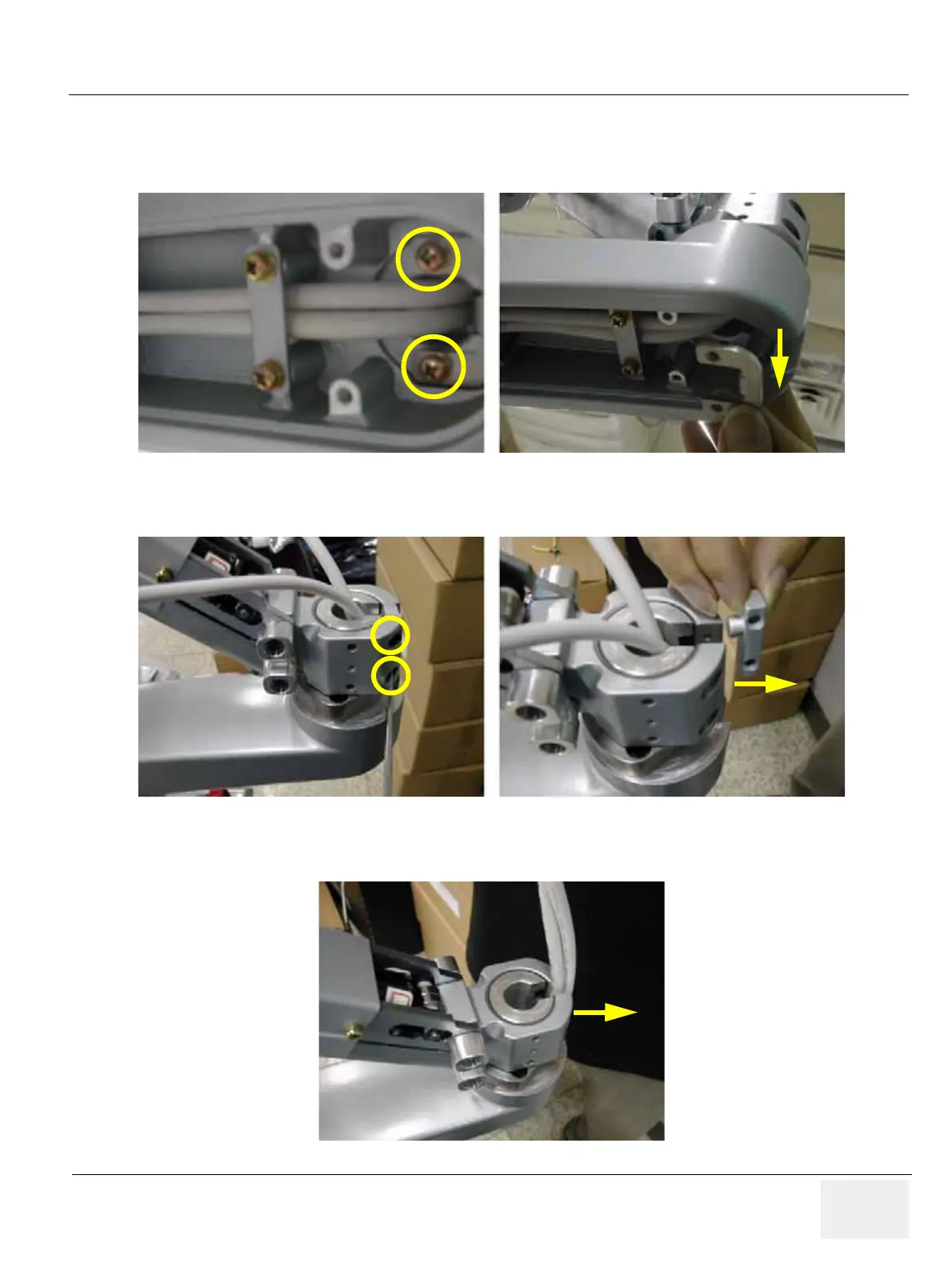
11.) Unscrew 2 screws (2159625, PH M4x8 W/SP) to remove the Lower arm guide bracket. Refer to
the figure below.
12.) Unscrew 2 screws (2159626, PH M4X20) to remove the Arm stopper. Refer to the figure below.
13.) Pull out power cable & DVI cable. Make sure flexible arm not to rotate. Refer to the figure below.
Figure 8-241 Removing the Lower arm guide bracket
Figure 8-242 Removing the Arm stopper
Figure 8-243 Pulling out power cable & DVI cable

 Loading...


