– 38 –
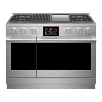
5. Slide the switch off the switch plate.
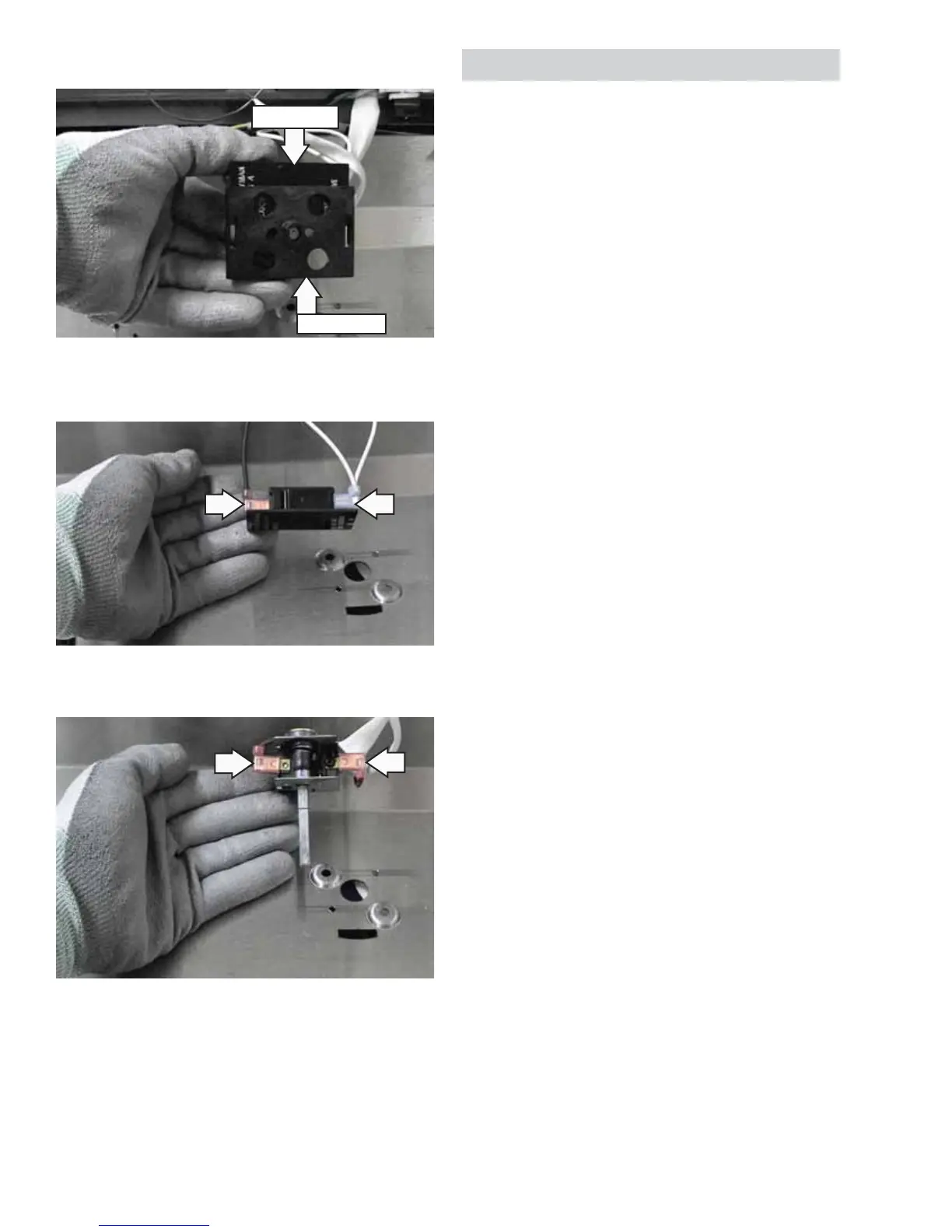
6. Remove wires from the LED switch.
7. Remove wires from the control.
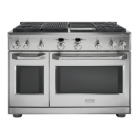
8. Slide the capillary out of the griddle burner box.
LED Switch
Switch Plate
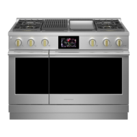
Grill and Griddle Ignition Systems
The grill and griddle burners are ignited by a glow-
bar ignition system. The igniter is a Norton style
rectangular glow-bar. The grill and griddle ignition
circuits consist of the control, an igniter, a hi limit
switch (griddle only), and a safety valve. These
components are wired in series for each cooking
function.
The most important points to know about the
ignition system are:
• THE IGNITER RESISTANCE DECREASES AS THE
IGNITER SURFACE TEMPERATURE INCREASES.
• THE SAFETY VALVE OPERATES BY CURRENT, NOT
VOLTAGE.
From a cold start, the igniter needs 30 to 60
seconds, with a minimum of 116 volts applied, to
reduce its electrical resistance enough to provide a
minimum of 2.9 amps of current fl ow in the series
circuit. This is the required current fl ow needed
for the safety valve to open and supply gas to the
burner.
The glow-bar should provide a steady current fl ow
of 3.4 to 3.6 amps (3.03 / 3.3 VAC) in the circuit. At
that point, the igniter temperature is 1800°F to
2500°F (982°C to 1371°C). The igniter will remain
energized at all times during burner operation. If
the igniter glows red but does not draw at least 2.9
amps, the fault is usually with the igniter, not the
valve.
Always check the gas shut-off valve located next to
the pressure regulator for a Not On condition.