– 39 –
Glow-bar Igniter
WARNING: The range and rangetop use rect-
angular Norton glow-bar igniters. They are NOT
INTERCHANGEABLE with cylindrical Carborundum
glow-bar igniters. The two types of glow-bar igniters
operate at different amperage and use different gas
valves.
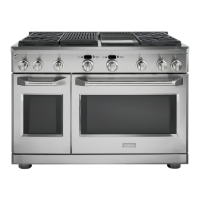
Check the glow-bar circuit with a clamp-on
ammeter. If igniter glows red but circuit does not
draw at least 2.9 amps, the fault is likely with the
igniter, not the valve.
Note: If igniter glows, but ignition does not occur, be
sure the gas shut-off valve on the pressure regulator
is in the open position.
Slow ignition can be caused by one or more of the
following conditions:
Blockage of primary air intake: Inlet slots under 1.
bullnose (near LED light locations) must be open.
Blockage of secondary air intake holes: 2.
Examine grill and griddle burner boxes (galva-
nized box surrounding burner) and inspect the
secondary holes beneath the burner for signs of
blockage.
Improper alignment of orifi ce hood and burner: 3.
Orifi ce must be pointing straight into burner
venturi.
Improper air/gas adjustment.4.
Blockage of griddle burner gas exit holes. 5.
Internal restriction or partial restriction inside
the grill burner assembly.
The ignitor should draw approximately 3.4 to 3.6 6.
amps when operating. To check, carefully use a
clamp-on ammeter at one of the igniter leads.
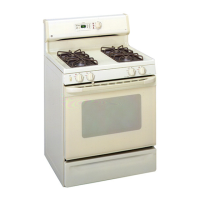
Grill Igniter Circuit Test
Caution: When removing the wire from the igniter,
make sure you do not damage the heat shrink
insulation on the wire. If damaged, repair the wire
insulation with fi berglass tape.
Lift each burner base, note the color of the 3.
igniter wire, then disconnect the igniter wire.
Surface Burner Base
Note: The following describes the procedure to
remove a single burner base. The procedure to
remove the remaining burner bases is identical.
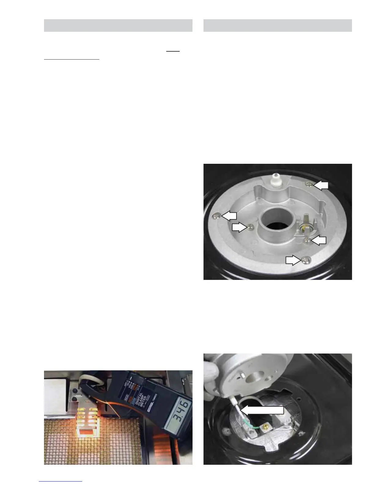
To remove the burner base:
Lift off the burner grates, cap, and burner head.1.
Note: Five T-15 Torx screws attach the surface
burner: 3 coarse thread screws on the outside, and
2 fi ne thread screws on the inside.
2. Remove the three T-15 Torx screws that attach
the burner base to the burner pan and the two
T-15 Torx screws that attach the burner base to
the burner.
Igniter Wire