– 60 –
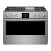
Oven Control Logic Board
The oven control logic board consists of several
boards and a frame. The logic board controls oven
operation through user input and feedback from the
oven sensor and switches. The oven control logic
board is attached to the inside center of the control
panel, and is only available as a complete assembly.
It is necessary to lower the control panel to replace
the oven control logic board.
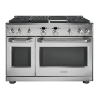
To remove the oven control logic board:
Remove the oven control knobs.1.
2. Place the control panel in the service position.
(See Control Panel.)
3. Remove the 3 Phillips-head screws (6 on double
oven models), that attach the oven control logic
board to the control panel, then carefully lift the
assembly from the control panel.
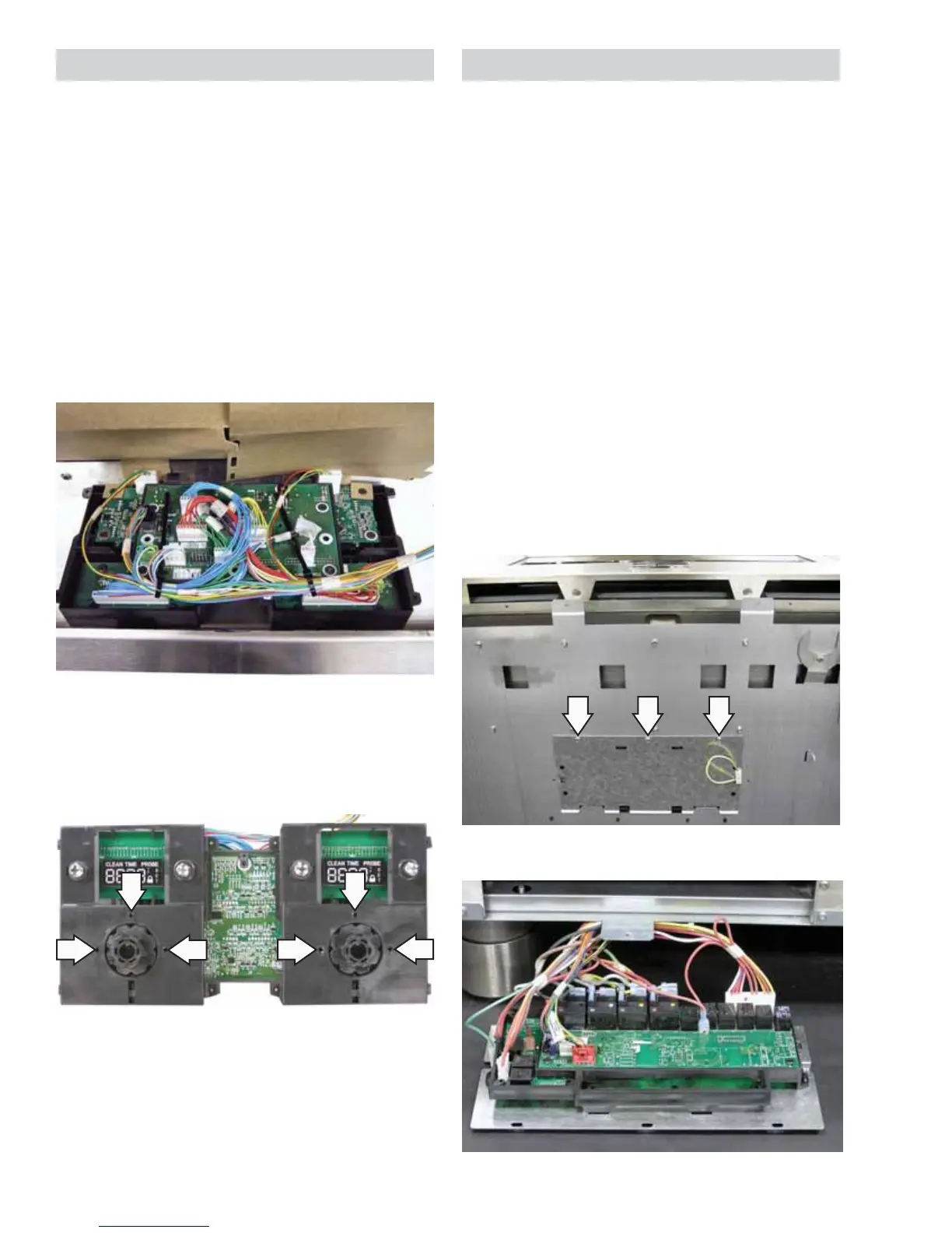
Screw Locations for Double Oven Models
Bottom View of Range
Service Position
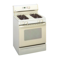
Oven Relay Board
The oven relay board is located below the oven
cavity and is accessed by removing a bottom panel
and lowering the board to the fl oor.
Note:
The board will not have enough clearance to •
slide out if the front leveling legs are in their
lowest position.
There is suffi cient wiring to pull the relay board •
out completely to the service position.
The majority of the connections are color coded •
to match the wiring.
Both the main and companion oven relay •
boards are accessed using the same method.
To access and place the oven relay board in the
service position it is necessary to remove the three
1/4-in. hex-head screws at the front and pull the
panel out from the tabs at the rear.