– 49 –
Sail
Sail Switch
Sail Switch
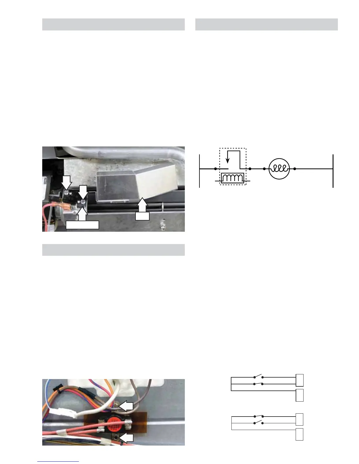
The sail switch is located at the top rear of the
range, above the cooling fan. This switch monitors
the presence of the airstream from the cooling fan.
If the sail switch is open when the fan should be
on, the logic board will disable power to all cooking
elements. (See Oven Sensor, Sail, and Door Switch
Test.)
The sail switch is attached to the cooling fan with
two 3/16-in. hex-head screws. To access the sail
switch from the front, remove the top back vent
trim. To replace the switch, it is necessary to remove
the range from its installation and remove the back
panel. (See Installation, Back Panel.)
Oven TCO
The oven TCO is located above the convection fan
motor. The TCO is wired in series with the common
side of all the elements, which are tied to the
common side of the double line break relay. The
TCO is used to protect against element runaway. If
open, the elements will not work for any operation.
The oven TCO open at 284°F (140°C), and is non-
resettable. When replacing an open TCO, determine
the cause and make the necessary repairs.
The oven TCO is attached to the range with two 1/4-
in. hex-head screws. To replace the oven TCO, it is
necessary to remove the range from its installation
and remove the back panel. (See Installation, Back
Panel.)
Lock Assembly
The motorized door lock assembly is located above
the oven. The assembly consists of a lock motor
cam and switch assembly, lock hook, mounting
plate, door switch, spring and plunger.
The lock motor is energized when the control is set
for Clean and Clean Time selected. The K13 relay
contact will close and complete the circuit that
supplies the voltage to the lock motor.
Door locking or unlocking will close and complete
the circuit that supplies voltage to the lock motor.
L
Door Locking/Unlocking Strip Circuit
Note: To enable proper operation of the door
lock, ensure that the door jamb switch contacts
“common” to “normally closed” are closed (door
closed position). This enables power to be delivered
when the door lock closes.
The cam on the motor performs two functions:
Positions the lock hook in the door to prevent 1.
opening during the Clean operation.
Operates the lock switches, which tell the 2.
control if the door is unlocked or locked and
ready for the Clean operation.
Note: When the door is either being locked or
unlocked, both the lock and unlock switches will be
in the open position. The LOCKED AND UNLOCKED
diagrams are representative of a single oven. On
double oven models, the diagrams apply to both
models, except for the pin position.
(See Oven Sensor,
Sail, and Door Switch Test section for reference to
double ovens).
J16
J17
Y
P
P
P
B
4
3
1
LOCK
UNLOCK
LOCKED
J16
J17
Y
P
P
P
B
4
3
1
LOCK
UNLOCK
UNLOCKED
(Continued next page)