– 76 –
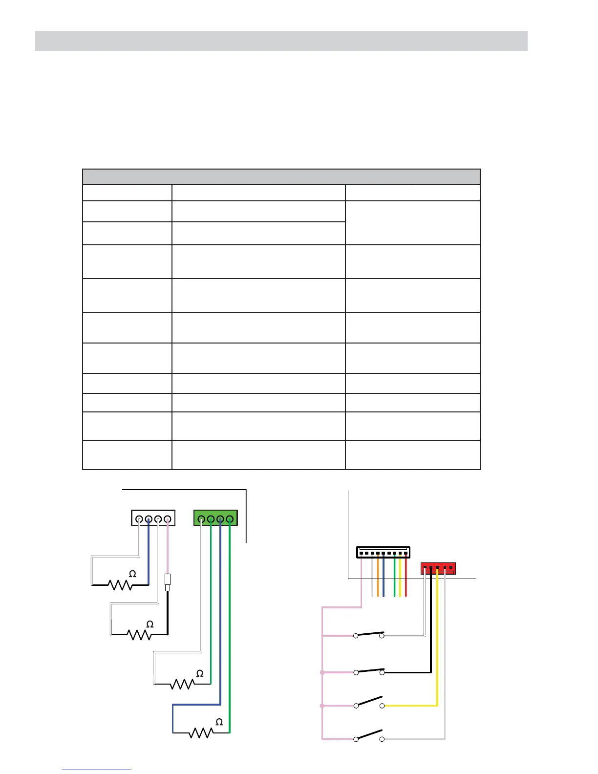
Oven Sensor, Sail, and Door Switch Test
Note: See Lock Assembly for door switch function explanation.
Remove power from oven. 1.
The resistance measurements are made on the main logic board at connector J5 and J6, and the oven 2.
relay board at connectors J16 and J17.
If abnormal reading is observed, wiggle leads at disconnect block. If any variation, replace. 3.
MAIN AND COMPANION OVENS
Circuit Terminals Ohms
Oven Sensor A Main Logic Board J5, pin 1 to pin 2 1091 Ω @ Rm. Temp.
1654 Ω @ 350°F
2634 Ω @ 865°F
Oven Sensor B Main Logic Board J5, pin 3 to pin 4
Door Latched Relay board J17 pin 1 to J16 pin 3
Relay board J17 pin 1 to J16 pin 4
0 Ω
Open
Door Unlatched Relay board J17 pin 1 to J16 pin 4
Relay board J17 pin 1 to J16 pin 3
0 Ω
Open
Sail Switch
Cooling Fan On
Relay board J17 pin 1 to J16 pin 5 0 Ω
Sail Switch
Cooling Fan Off
Relay board J17 pin 1 to J16 pin 5 Open
Meat Probe A Main Logic Board J6, pin 1 to pin 2
30-50K Ω @ Rm. Temp.
Meat Probe B Main Logic Board J6, pin 3 to pin 4
30-50K Ω @ Rm. Temp.
Door Status
Door Open
Relay Board J17 pin 1 to J16 pin 2 0 Ω
Door Status
Door Closed
Relay Board J17 pin 1 to J16 pin 2 Open
Large Oven
Small Oven
Large Oven
Small Oven
MAIN LOGIC BOARD
W
N
W
P
GG
1
4
J6
12
3
4
12
3
4
1
4
J5
OVEN SENSOR
1080
OVEN SENSOR
1080
MEAT PROBE
30K - 50K
TIP
GND
MEAT PROBE
30K - 50K
TIP
GND
W
N
W
B
J16
J17
1
W
B
Y
S
PSO
N
G
YR
9
1
5
RELAY BOARD
P
B
Y
S
DOOR STATUS
DOOR LOCK
DOOR UNLOCK
SAIL SWITCH