GFK-1504K Chapter 6 Expansion Modules 6-3
6
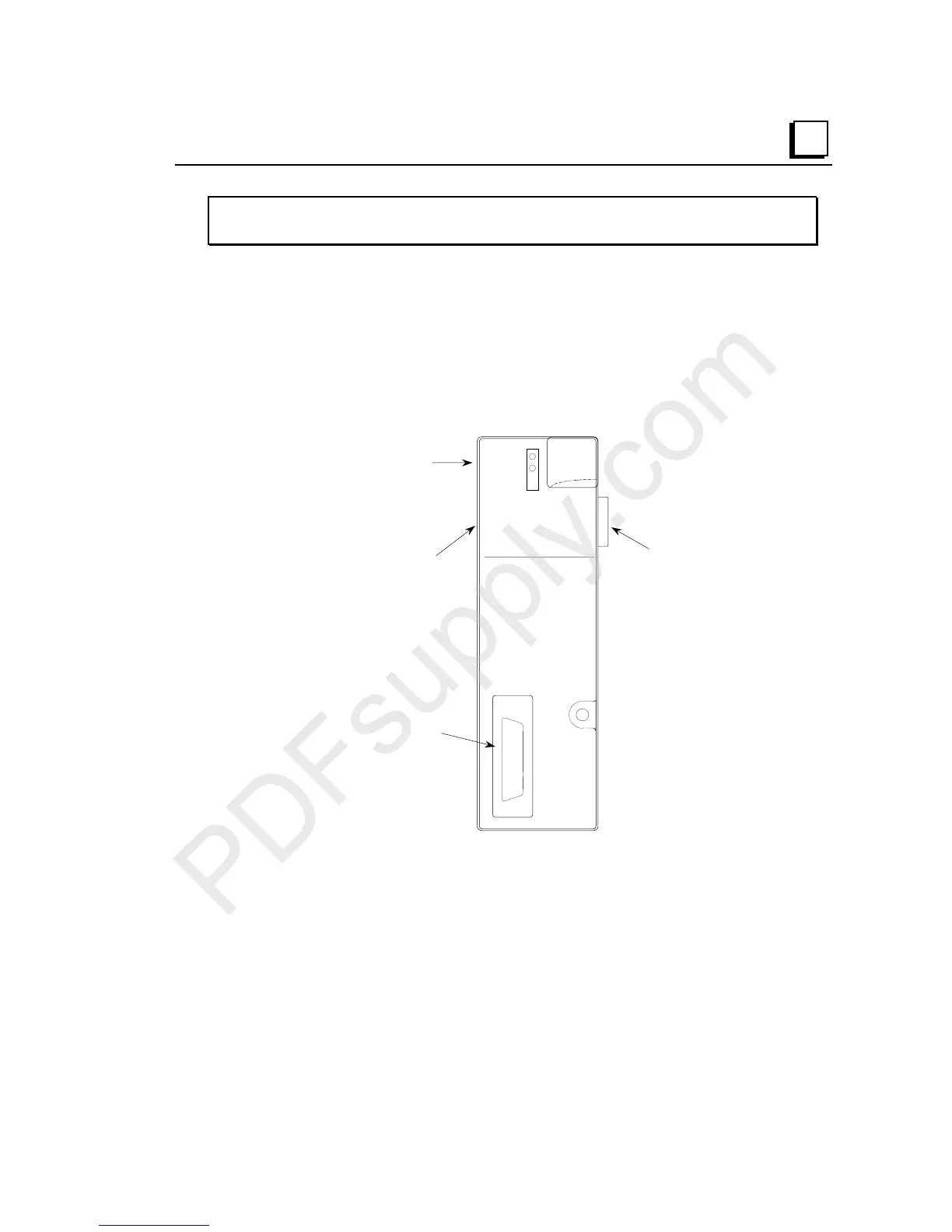
IC200ETM001
Expansion Transmitter Module
Connectors
The 26-pin female D-shell connector on the front of the Expansion Transmitter is the
expansion port for connecting to an Expansion Receiver Module.
The 16-pin male connector on the upper left side of the Expansion Transmitter is the
pass-though serial programming port. It can be used to upload firmware updates to
an adjacent NIU.
Expansion
Port to
Bus
Receiver
Module
Firmware
Update
Serial Port
LEDs
CPU/NIU
Mating
Connector
PWR
EXP TX
.
.
.
.
.
.
.
.
.
.
.
.
.
.
.
.
.
.
.
.
.
.
.
.
.
.
EXP 1
LED Indicators
The LEDs on the Expansion Transmitter show the status of power to the module and
the status of the expansion port.
The PWR LED is On when the module is receiving 5VDC power from the CPU or
NIU. It is Off when the module is detached from the CPU/NIU or when the
CPU/NIU itself is not receiving power.
The EXP TX LED is either blinking or On when the Expansion Transmitter is
communicating with the Bus Receiver Modules connected to it through the
expansion bus link. It is Off when they are not communicating.