2-28 VersaMax® Modules, Power Supplies, and Carriers User's Manual – March 2003 GFK-1504K
2
Disconnect-Style Interposing I/O Terminals,
Wiring for Modules with One Group per Row
This wiring format generally applies when the associated VersaMax module provides for
connection of I/O in 16-point groups. An example of such a module is the VersaMax
24VDC 16pt Output Module, IC200MDL740:
Q1
Q2 Q3
Q4
Q5 Q6 Q7 Q8
Q9 Q10 Q11 Q12 Q13 Q14 Q15 Q16
123456789 111213141516171810
A
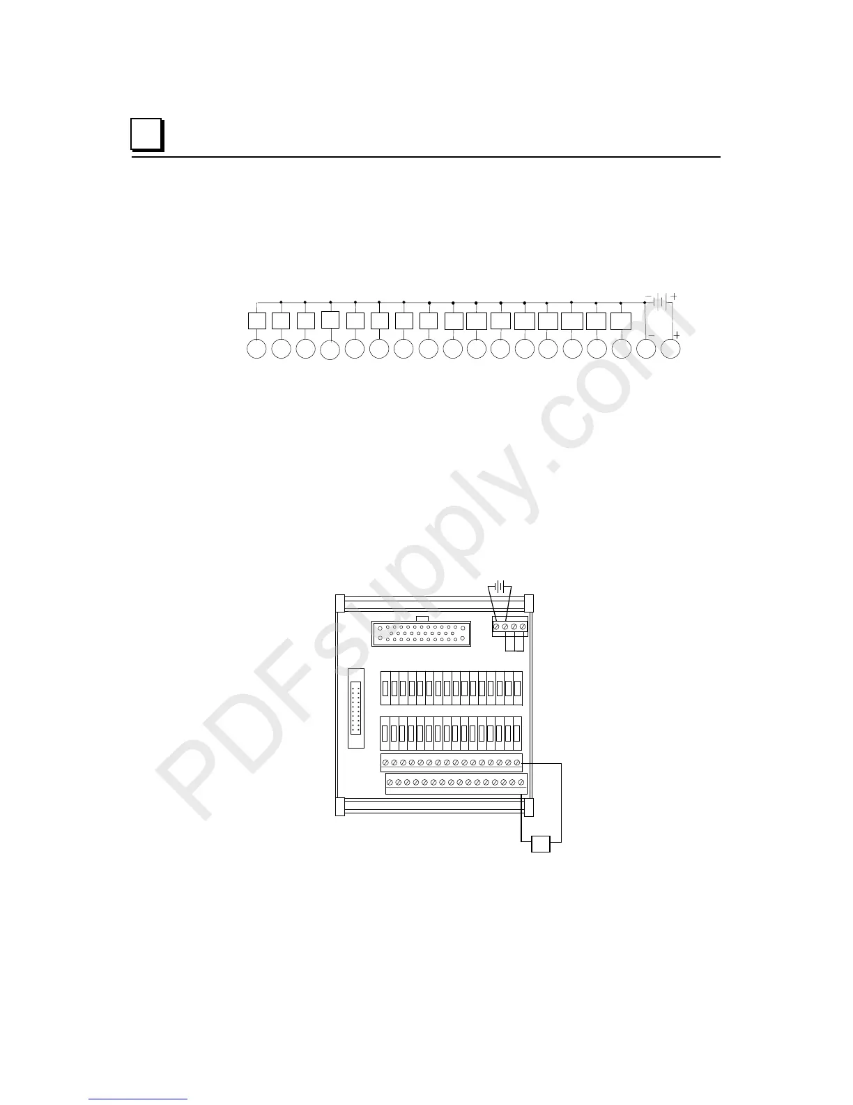
When connecting an Interposing Disconnect base in this format, follow these guidelines:
Connect the field devices to A1-A16 (or B1-B16 where appropriate)
Connect the return wires of field devices to the corresponding common connections –
A1 to W1, A2 to W2, A9 to X1, A10 to X2, etc.
Connect jumpers between the A17, W, and X terminals (or B17, Y, and Z)
Connect the power supply between A17 and A18 (or B17 and B18)
Example: Wiring for Output Module IC200MDL740
Example field wiring for IC200CHS101 when used with VersaMax modules with 1 group
per terminal row
J1
J2
Q1
A16A15A14A13A12A11A10A9A8A7A6A5A4A3A2A1
X8 X7 X6 X5 X4 X3 X2 X1 W8 W7 W6 W5 W4 W3 W2 W1
A18 A17 X W