13-12 VersaMax® Modules, Power Supplies, and Carriers User's Manual – March 2003 GFK-1504K
13
IC200MDD841
Mixed Module, 24VDC Positive Logic Input 20 Points / Output 12 Point /
(4) High Speed Counter, PWM, or Pulse Train Configurable Points
Type
B Counter
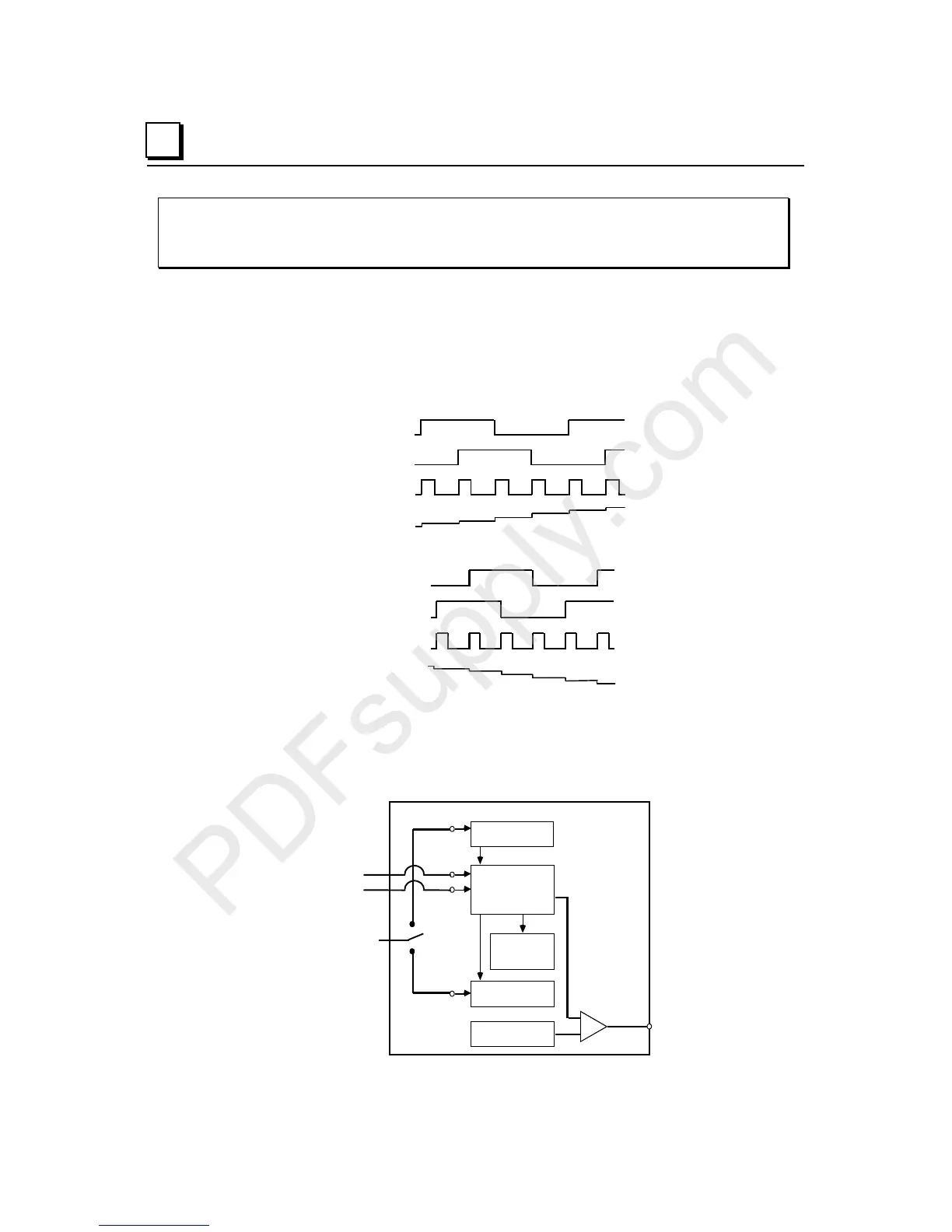
The Type B counter uses two counter input signals for A-Quad-B counting. The phase
relationship between the counter inputs (A & B) determines whether the accumulator is
incremented or decremented on a transition of either counter input.
The count direction is up if A leads B.
COUNT
N
Accumulator
N + 6
The count direction is down if A lags B.
Accumulator
Value
A
B
COUNT
N
N + 6
The Type B counter has a Strobe register, a Preload register, a 16-bit Accumulator, and a
Counts-per-Timebase register. These operate as described for Type A counters.
The Type B counter can have one output that is activated based on selected On and Off
preset values.
U
/Down Counter
Preload Value
16 bit
Strobe Register
Counts Per
Time Base
(16*bit)
Accumulator
16 bit
On/Off Presets
OUTPUT
PRELOAD
STROBE
PRELOAD
STROBE
INPUT
COUNT B
COUNT A