8-30 VersaMax® Modules, Power Supplies, and Carriers User's Manual – March 2003 GFK-1504K
8
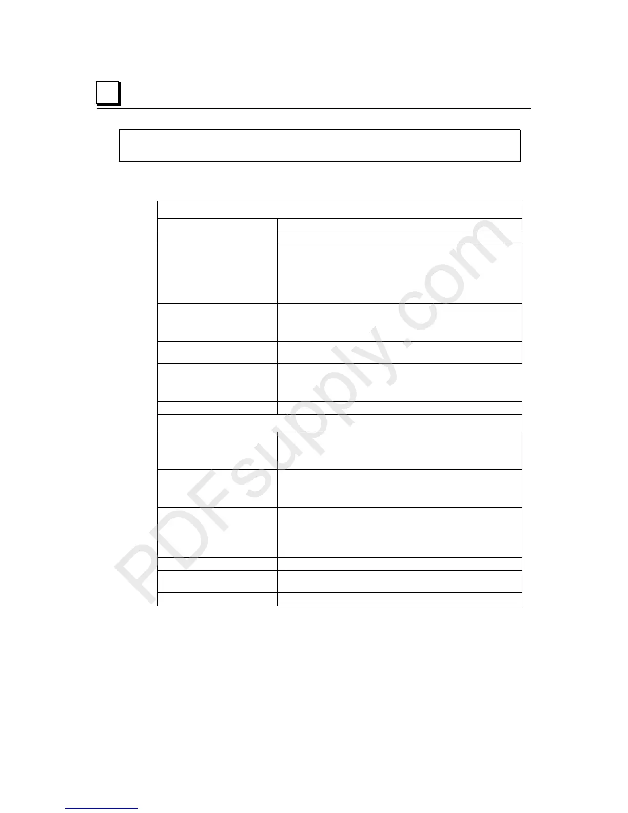
IC200MDL743
Output Module, 5/12/24V DC Negative Logic 0.5 Amp, 16 Points
Module Specifications
Module Characteristics
Points 1 group of 16 outputs
Module ID FFFF8080
Isolation:
User input to logic (optical)
and to frame ground
Group to group
Point to point
250VAC continuous; 1500VAC for 1 minute
Not applicable
None
LED indicators One LED per point shows individual point on/off state
FLD PWR LED indicates field power is present
OK LED indicates backplane power is present
Backplane current
consumption
5V output: 70mA maximum
External power supply:
5VDC-TTL mode
12/24VDC mode
+4.75 to +5.25VDC, +5VDC nominal
+10.2 to +30VDC, +12/24VDC nominal
Thermal derating No derating required.
Output Characteristics
Output voltage:
5VDC-TTL mode
12/24VDC mode
+4.75 to +5.25VDC, +5VDC nominal
+10.2 to +30VDC, +12/24VDC nominal
Output voltage drop:
5VDC-TTL mode
12/24VDC mode
0.4V maximum
0.3V maximum
Load current:
5VDC-TTL mode
12/24VDC mode
25mA maximum
0.5A at 30VDC maximum (resistive)
2.0A inrush maximum for 100ms
Output leakage current 0.5mA at 30VDC maximum
On response time
Off response time
0.2ms maximum
1.0ms maximum
Protection (each output) No internal fuse