9-4 VersaMax® Modules, Power Supplies, and Carriers User's Manual – March 2003 GFK-1504K
9
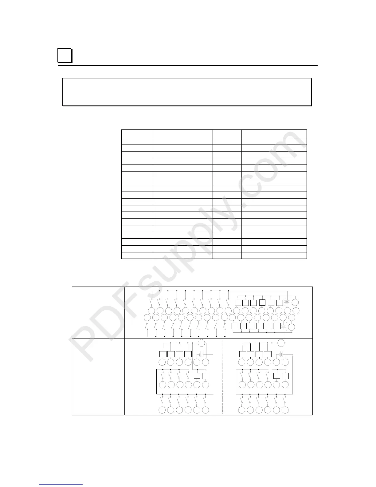
IC200MDD840
Mixed Module, 24VDC Positive Logic Input 20 Points /
Output Relay 2.0 Amp 12 Points
Field Wiring
Terminal Connection Terminal Connection
A1 Input 1 B1 Input 11
A2 Input 2 B2 Input 12
A3 Input 3 B3 Input 13
A4 Input 4 B4 Input 14
A5 Input 5 B5 Input 15
A6 Input 6 B6 Input 16
A7 Input 7 B7 Input 17
A8 Input 8 B8 Input 18
A9 Input 9 B9 Input 19
A10 Input 10 B10 Input 20
A11
Output 1
B11
Output 7
A12
Output 2
B12
Output 8
A13
Output 3
B13
Output 9
A14
Output 4
B14
Output 10
A15
Output 5
B15
Output 11
A16
Output 6
B16
Output 12
A17 Inputs 1-10 Common B17 Inputs 11-20 Common
A18 Outputs 1-6 Common B18 Outputs 7-12 Common
When wiring outputs to inductive loads, use of external suppression circuits is
recommended. See chapter 2, "Installing Wiring for I/O Devices-Wiring to Inductive
Loads" for more information.
Wiring Connections
for Carriers with Two
Rows of Terminals
IC200CHS002, 005
IC200CHS012, 015
I1
I2
I3 I4 I5 I6 I7 I8
9I10
I11 I12 I13 I14
Q1 Q2 Q3
Q4
Q5 Q6
Q7 Q8 Q9
Q10 Q11 Q12
V
I17 I18 I19 I20
I15 I16
V
123456789 1112131415161718
1 2 3 4 5 6 7 8 9 111213141516 171810
10
B
A
Wiring Connections
for Carriers with
Three Rows of
Terminals
IC200CHS001, 022, 025
IC200CHS011
123456
789 111210
A
13 14 15 16 17 18
I1 I2 I3 I4 I5 I6
Q3 Q4 Q5 Q6
+
-
Q1 Q2
I7 I8 I9 I10
V
123456
789 111210
B
13 14 15 16 17 18
I11 I12 I13 I14 I15 I16
Q9 Q10 Q11 Q12
+
-
Q7 Q8
I17 I18 I19 I20
V