2-32 VersaMax® Modules, Power Supplies, and Carriers User's Manual – March 2003 GFK-1504K
2
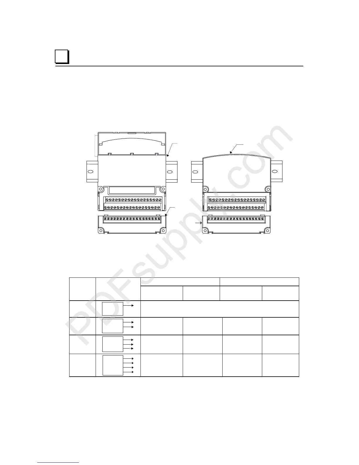
Wiring for Auxiliary I/O Terminals
Auxiliary I/O Terminals can be used to provide extra field wiring connections if needed.
They can be attached to either a terminal-style I/O carrier or to Interposing I/O Terminals.
Auxiliary I/O Terminals units are available with 18 box-style terminals (as shown below)
or with 18 spring style terminals or 12 barrier-style terminals.
CLASS I ZONE 2 Ex nA IIC T4 OC Ta
Ex nV II T4 De mko
Terminal-Style
Auxiliary I/O
Interposing
Auxiliary I/O
Terminals
The terminals are electrically tied together. There is no electrical connection from the I/O
Carrier or Interposing Terminals to the Auxiliary I/O Terminals; any necessary electrical
reference must be provided. Multiple Auxiliary I/O Terminals can be connected together
to provide the additional wiring terminals that may be needed for high-density modules, or
for 2-, 3-, and 4-wire field devices.
16 Point Module 32 Point ModuleField
Device
Diagram
Box-, Spring-, or
Connector Carrier
Barrier-Style
Carrier
Box-, Spring-, or
Connector Carrier
Barrier-Style
Carrier
1-wire
Point
no Auxiliary Terminals
2-wire
Point
Common
1 Auxiliary
Terminals *
3 Auxiliary
Terminals
2 Auxiliary
Terminals *
3 Auxiliary
Terminals
3-wire
Point
Common
+V
2 Auxiliary
Terminals *
6 Auxiliary
Terminals
4 Auxiliary
Terminals *
6 Auxiliary
Terminals
4-wire
Point
Common
+V
-V
3 Auxiliary
Terminals *
9 Auxiliary
Terminals
6 Auxiliary
Terminals *
9 Auxiliary
Terminals
* for 16-point modules that only use one row of terminals for point wiring, a shorting bar may be used
to provide extra terminals. See the heading
Using A Shorting Bar
in this chapter.