9-50 VersaMax® Modules, Power Supplies, and Carriers User's Manual – March 2003 GFK-1504K
9
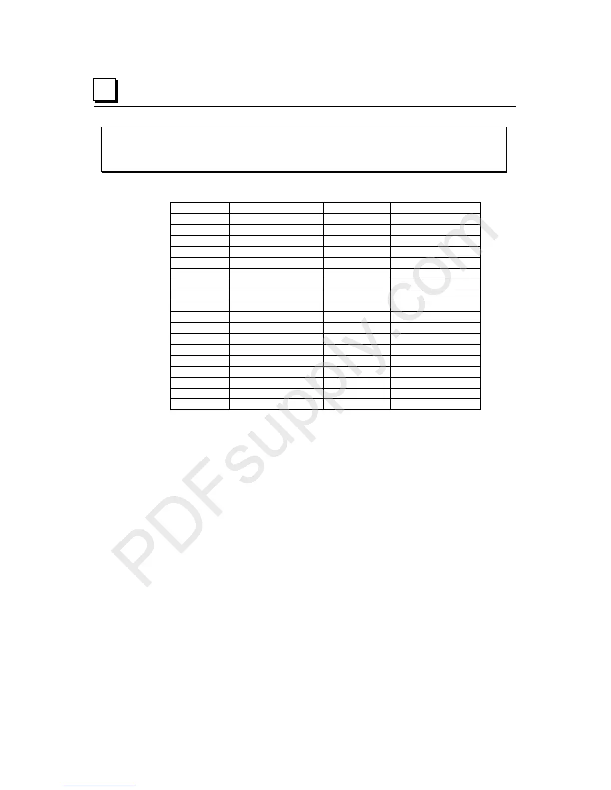
IC200MDD851
Mixed Module, Output 12/24VDC Positive Logic Grouped
16 Points / Input 5/12VDC Pos/Neg Logic Grouped 16 Points
Field Wiring
Terminal Connection Terminal Connection
A1 Output 1 B1
Input 1
A2 Output 2 B2
Input 2
A3 Output 3 B3
Input 3
A4 Output 4 B4
Input 4
A5 Output 5 B5
Input 5
A6 Output 6 B6
Input 6
A7 Output 7 B7
Input 7
A8 Output 8 B8
Input 8
A9 Output 9 B9
Input 9
A10 Output 10 B10
Input 10
A11 Output 11 B11
Input 11
A12 Output 12 B12
Input 12
A13 Output 13 B13
Input 13
A14 Output 14 B14
Input 14
A15 Output 15 B15
Input 15
A16 Output 16 B16
Input 16
A17 DC - B17
Inputs 1-8 Common
A18 DC + B18
Inputs 9-16 Common
The 16 inputs form two groups of 8. Each group has a common connection. When wiring
outputs to inductive loads, use of external suppression circuits is recommended. See
chapter 2, "Installing Wiring for I/O Devices-Wiring to Inductive Loads" for more
information.