GFK-1504K Chapter 9 Discrete Mixed Modules 9-33
9
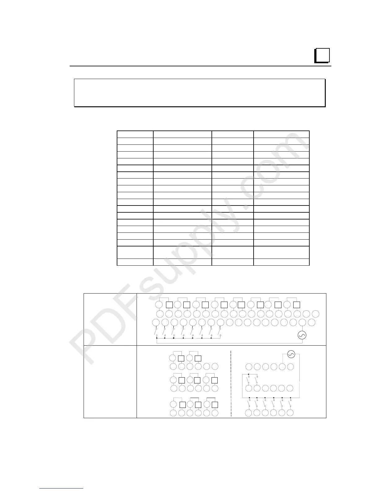
IC200MDD847
Mixed Module, Output Relay 2.0A per Pt Isolated 8 Points /
Input 240VAC Grouped 8 Points
Field Wiring
Terminal Connection Terminal Connection
A1 Output 1-1 B1 Input 1
A2 Output 1-2 B2 Input 2
A3 Output 2-1 B3 Input 3
A4 Output 2-2 B4 Input 4
A5 Output 3-1 B5 Input 5
A6 Output 3-2 B6 Input 6
A7 Output 4-1 B7 Input 7
A8 Output 4-2 B8 Input 8
A9 Output 5-1 B9 No connection
A10 Output 5-2 B10 No connection
A11 Output 6-1 B11 No connection
A12 Output 6-2 B12 No connection
A13 Output 7-1 B13 No connection
A14 Output 7-2 B14 No connection
A15 Output 8-1 B15 No connection
A16 Output 8-2 B16 No connection
A17 No connection B17 Inputs 1-8 Common
(Return)
A18 No connection B18 No connection
Outputs are individually isolated. When wiring outputs to inductive loads, use of external
suppression circuits is recommended. See chapter 2, "Installing Wiring for I/O Devices-
Wiring to Inductive Loads" for more information.
Wiring Connections
for Carriers with Two
Rows of Terminals
IC200CHS002, 005
IC200CHS012, 015
Q1 Q2 Q3 Q4 Q5 Q6 Q7 Q8
v v v v v v v v
I1 I2 I3 I4 I5 I6 I7 I8
N
H
1 2 3 4 5 6 7 8 9 111213141516 1718
123456789 111213141516171810
10
B
A
Wiring Connections
for Carriers with
Three Rows of
Terminals
IC200CHS001, 022, 025
IC200CHS011
123456 123456
13
14 15 16 17 18
789 111210
A
13 14 15 16 17 18
789 111210
I1 I2 I3 I4 I5 I6
I7
I8
B
Q4 Q5 Q6
Q7 Q8
vvv
vv
Q1 Q2 Q3
vv
v
NH
 Loading...


