11-26 VersaMax® Modules, Power Supplies, and Carriers User's Manual – March 2003 GFK-1504K
11
IC200ALG325
Analog Output Module, 13 Bit Voltage 8 Channels
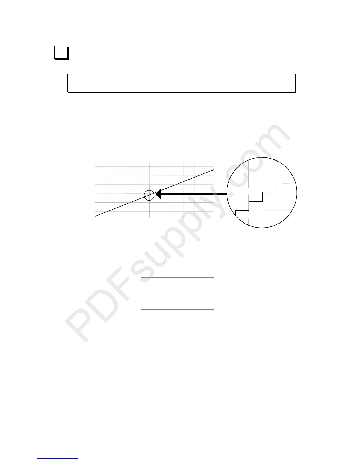
Scaling for Unipolar Outputs
The graph below shows the relationship between the output voltage measured at the field
terminals and the data that is output by the module, when outputs are set up for the
unipolar range.
Count vs Output Voltage, Unipolar
0 3200 6400 9600 12800 16000 19200 22400 25600 28800 32000
12
11
10
9
8
7
6
5
4
3
2
1
0
Count
Voltage
5.0075V
5.00875V
16032
16028
16024
16020
5.00625V
5.0100V
4 counts =
1.25mV
Voltage can be calculated using the following equation:
Vout = ( (analog counts x 10.24) / 32768 )
The count value must be a multiple of 4. If the module receives a count value that is not a
multiple of 4, it rounds the value down to the closest multiple of 4. For example:
Count Voltage
16024 5.0075V
16026 5.0075V
16028 5.00875V