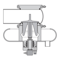
• Faire glisser le raccorde-
ment de rinçage (V9)
équipé de joints toriques
(7) sur la douille de l'en-
traîneur (6).
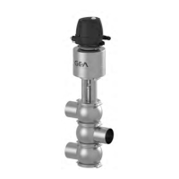
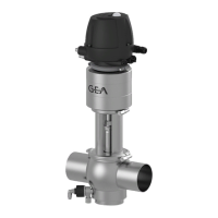
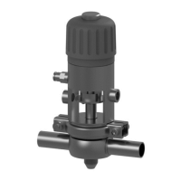
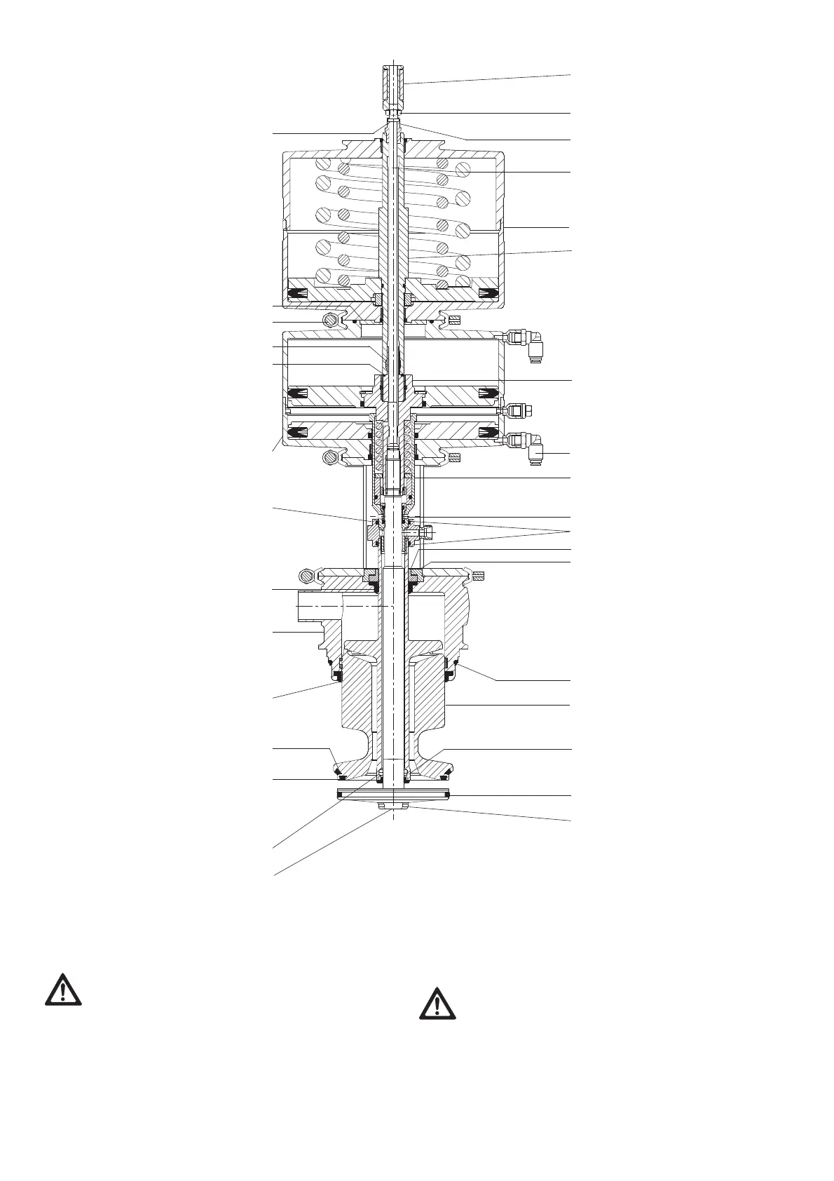
Vanne T_RL
• Equiper le double obtura-
teur (12) avec les bagues
trapézoïdales (23, 24), le
gicleur de nettoyage (13),
le boîtier de fuite (21), le
joint torique (11), la bague
d'étanchéité (22), le palier
(8), la garniture de palier
(9).
Vanne T_RC
• Equiper le double obtura-
teur (12) avec les joints
trapézoïdaux (23, 24), le
joint d'étanchéité à déclic
avec joint torique (13), le
boîtier de fuite (21), le
joint torique (11), la bague
d'étanchéité (22), le palier
(8), la garniture de palier
(9).
• Tenir la douille de
l'entraî neur avec une clé à
ergot en (Z) et serrer à
fond le double obturateur
en (W) à l'aide d'une clé à
pipe.
• Tenir l'entraîneur (26) avec
une clé à pipe, ouverture
36, et visser à fond en C le
disque de vanne (15) avec
le joint trapézoïdal monté
(14).
• Insérer le bourrelet de fer-
meture (17) dans l'entraî-
nement de levage (20).
• Fixer le bloc coulissant (3)
avec une bague de guida-
ge (16) à l'aide d'un man-
drin (4 mm) au niveau de
la tige de piston (27) de
l'action neur (5).
• Placer l'actionneur (5)
dans l'actionneur de leva-
ge (20) et le fixer avec l'an-
neau rabattable (10).
• Push rinsing connection
(V9) equipped with
O-rings (7) on to the
drive sleeve (6).
Valve T_RL
• Equip double-disk (12)
with V-rings (23, 24),
cleaning nozzle (13),
leakage housing,
O-ring (11), seal ring
(22), bearing (8) and
bearing disk (9).
Valve T_RC
• Equip double-disk (12)
with V-rings (23, 24),
snap seal with O-ring
(13), leakage housing
(21), O-ring (11), seal
ring (22), bearing (8)
and bearing disk (9
• Hold drive sleeve with
hook spanner at (Z) and
tighten double-disk by
inserting a tubular hex.
box spanner at (W).
• Hold striker (26) with
tubular hex. box span-
ner size 36 and tighten
valve disk (15) together
with installed V-ring
(14) at wrench face C.
• Insert locking flange
(17) into the lifting actu-
ator (20).
•
• Fix slider (3), complete
with rod guide ring (16)
at the piston rod (27) of
the actuator (5) using a
mandrel (4 mm).
• Insert actuator (5) into
the lifting actuator (20)
and fix with hinged
clamp (10).
ATTENTION
Lors du montage, ne pas endommager les aimants dans
la tige de commutation !
• Placer la tige de commutation (1) à travers la tige de
piston (27) et bloquer par contre-écrou contre le disque
de vanne (15), voir Liste des pièces de rechange/
schéma des dimensions tige de commutation (annexe).
CAUTION
Take care not to damage the magnet in the
switch bar!
• Put the switch bar (1) through the piston rod (27) and
lock with valve disk (15), see spare parts list/dimen-
sion sheet switching bar (annex).
1
6
Z
12
7
V9
24
C
23
13
20
22
21
22
8
9
W
26
14
15
11
19
18
17
10a
27
5
2
3
4
16
X
2015-09 · Vanne de fond à double siège T_R / T_RL / T_R / Mixproof Bottom Valve T_R / T_RL / T_RC
36

 Loading...