181
3. TACHOMETER MALFUNCTION
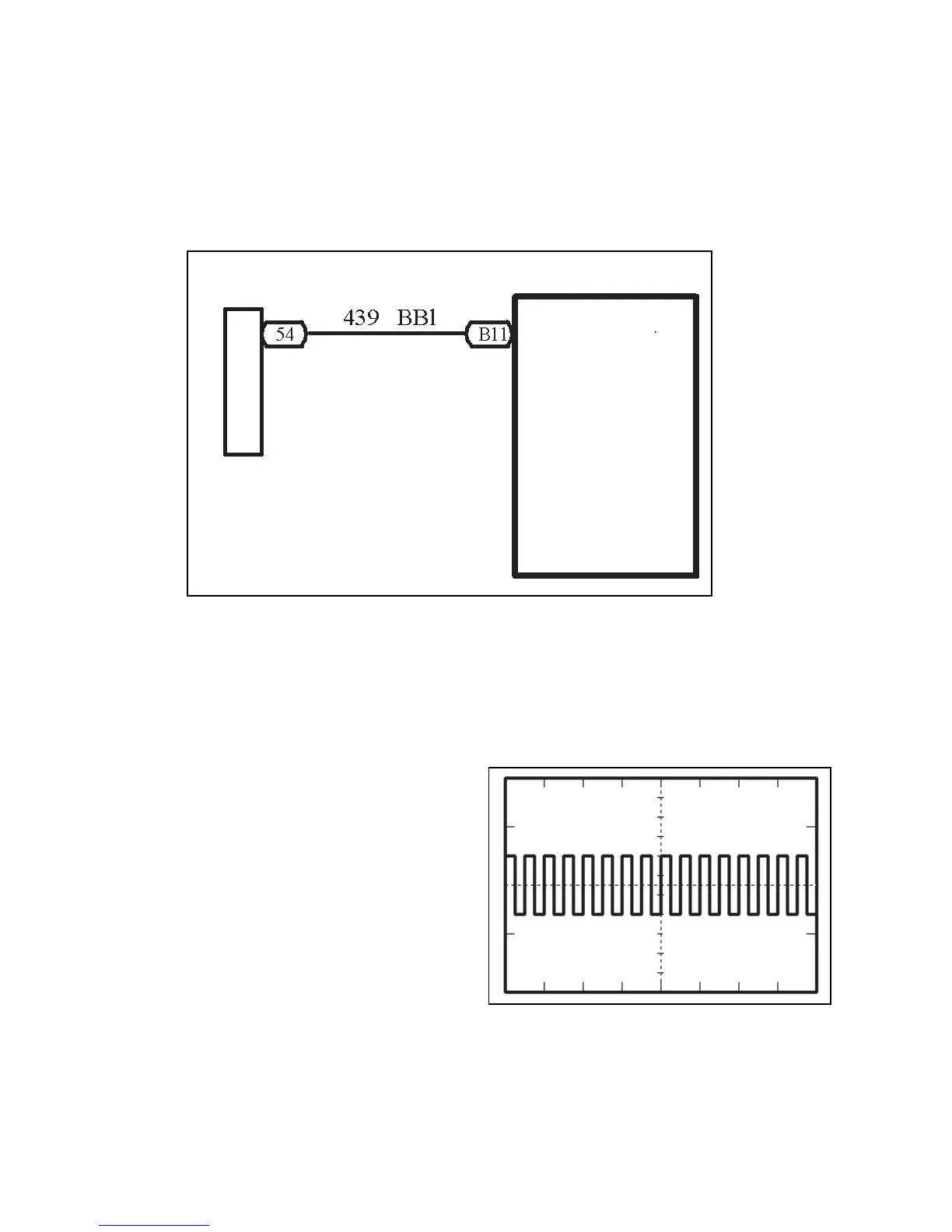
CIRCUIT DIAGRAM
Inspection procedure
(a) Inspect the combination meter assembly revolution input signal
1 Remove the combination meter assembly and retain the connection of connectors.
2 Connect the oscilloscope to the terminal B11 and
ground.
3 Start the engine
4 Inspect the signal wave form
Standard:
Show the correct wave form
Result and solution:
Normal Inspect and replace the combination
meter assembly
Abnormal Inspect the engine ECU revolution out-
put signal
Engine ECU
Combined Meter Assembly
Engine Revolution Signal