224
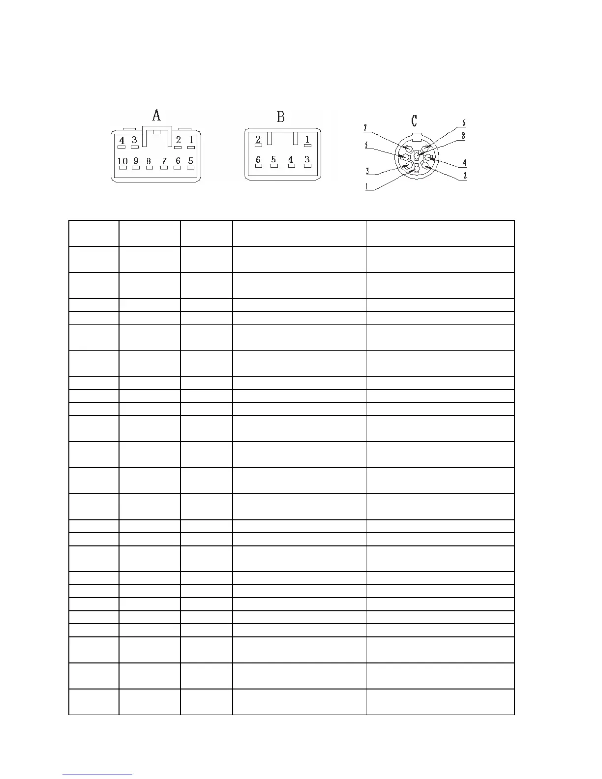
Section 2 Audio System Connector Terminal Layout
1. Connector terminal layout on wire harness
2. Connect terminal definition
Terminal
No.
Function Wire color Condition Standard Voltage
A1 FR+ Lg The audio system is on
Wave form is synchronized with
the output sound
A2 FL+ YB The audio system is on
Wave form is synchronized with
the output sound
A3 ACC RW Ignition switch turned to ACC 10
~
14V
A4 B+ R Constant Status 10
~
14V
A5 FR- LgR The audio system is on
Wave form is synchronized with
the output sound
A6 FL- Y The audio system is on
Wave form is synchronized with
the output sound
A7 GND B Constant Status Continuity
A8 Null
A9 Null
A10 TAIL GW
Position lamp switch turned to
ON
10
~
14V
B1 RR+ PB The audio system is on
Wave form is synchronized with
the output sound
B2 RL+ YR The audio system is on
Wave form is synchronized with
the output sound
B3 RR- P The audio system is on
Wave form is synchronized with
the output sound
B4 Null
B5 Null
B6 RL- YW The audio system is on
Wave form is synchronized with
the output sound
C1 B+ Constant Status 10
~
14V
C2 BUS Audio system is On Pulse Signal
C3 GND Constant Status Continuity
C4 ACC Ignition switch ACC 10
~
14V
C5 Null
C6 R-OUT The audio system is on
Wave form is synchronized with
the output sound
C7 L-OUT The audio system is on
Wave form is synchronized with
the output sound
C8
GND(Audio
Frequency)
Constant Status Continuity