301
4. Heater
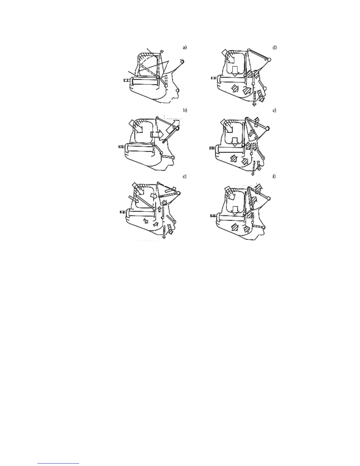
Figure 5 Heater Door Control Diagram
The heater comprises the heater radiator (heat exchanger), the plastic case forming the air duct, connecting
rods adjusting different air ducts and the door. The two groups of combination doors in the heater case are
connected to the heating control mechanism by the cable. The first group is the two couple action doors
adjusting the air mix ratio that are located in the outlet and inlet each; the second group comprises 4 doors
controlling the air outlet vents, where the upper center one controls the front outlet vent, each of the upper
left and right sides controls a defogger outlet vent and lower foot outlet vent. Figure 5 shows the working
principle of temperature adjustment door. The d) , c) , e) , f) in the figure indicate the outlet air flow direction
as the result of the adjustment of the control knob in the heating control mechanism panel.
Hot Wind Location
Cold Wind Location
Linkage
Radiator Core
Radiator Core
Temperature Adjustment
Door Working Principle
Foot Outlet
To Front Outlet
To Defroster
Radiator Core
To Front Outlet
Radiator Core
Foot Outlet
Foot Outlet
To Defroster