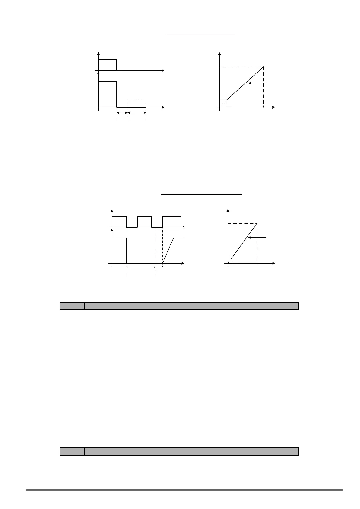
Figure4.4.60DCbrakingtostop
Output
frequency
Run
Time
Time
Stop
tb.b t
DCDB
tb.b :Minimum baseblock time (07 -18)
t
DCDB
:DC braking time
10
%
07-08 × 1
07-08 × 10
100
%
t
DCDB
Maximum output
frequency
(Fmax, 01- 02)
Output frequency
upon stop command
07-09=3: Coast to stop with timer
When a stop command is issued the motor will coast to a stop after the minimum Baseblock time (07-18) has
expired. The inverter ignores the run command until the total time of the timer has expired.
The total time of the timer is determined by the deceleration time (00-15, 17, 22 or 24) and the output frequency
upon stop. Refer to Figure 4.4.61
Figure4.4.61Coasttostopwithtimer
Output
frequency
Run
Time
Time
Stop
10% 100%
Maximum output
frequency
(Fmax, 01- 02)
Run Stop Run
T1
T1:Total Time
T1
Deceleration
Time
(e.g. 00-15)
Min.
baseblock
Time t
b.b
(07-18)
Output frequency
upon stop command
Code Parameter Name / Range
07-13 Low voltage detection level
200V: 150~210Vdc
400V: 300~420Vdc
07-25 Low voltage detection time
0.00~1.00 s
Adjust the 07-13 voltage level from 150 to 300 Vdc (
230V class) or from250 to 600 Vdc (400V class).
When the AC input voltage is lower than the 07-13 value (07-13/ 1.414 = AC voltage detection level) for the
time specied in 07-25 the low-voltage error “UV” will displayed. If 07-25 = 0.00 sec., the UV error will be dis-
played immediately.
Set preventive measures:
- The inverter input voltage will limit the output voltage. If the input voltage drops excessively, or if the load is
too big, the motor may stall.
- If the input voltage drops below the value set in 07-13 then the output is turned off momentarily. The inverter
will not automatically start when power is restored.
Code Parameter Name / Range
07-14 Pre-excitation time
0.00~10.00 s
VDI100 • Instruction manual
195

 Loading...


