Figure4.4.58Decelerationtostop
Run Stop
Deceleration
Ramp to stop
T
n Command
t Frequency
07-06
Time
Time
T: DC Braking Time at stop (07-08)
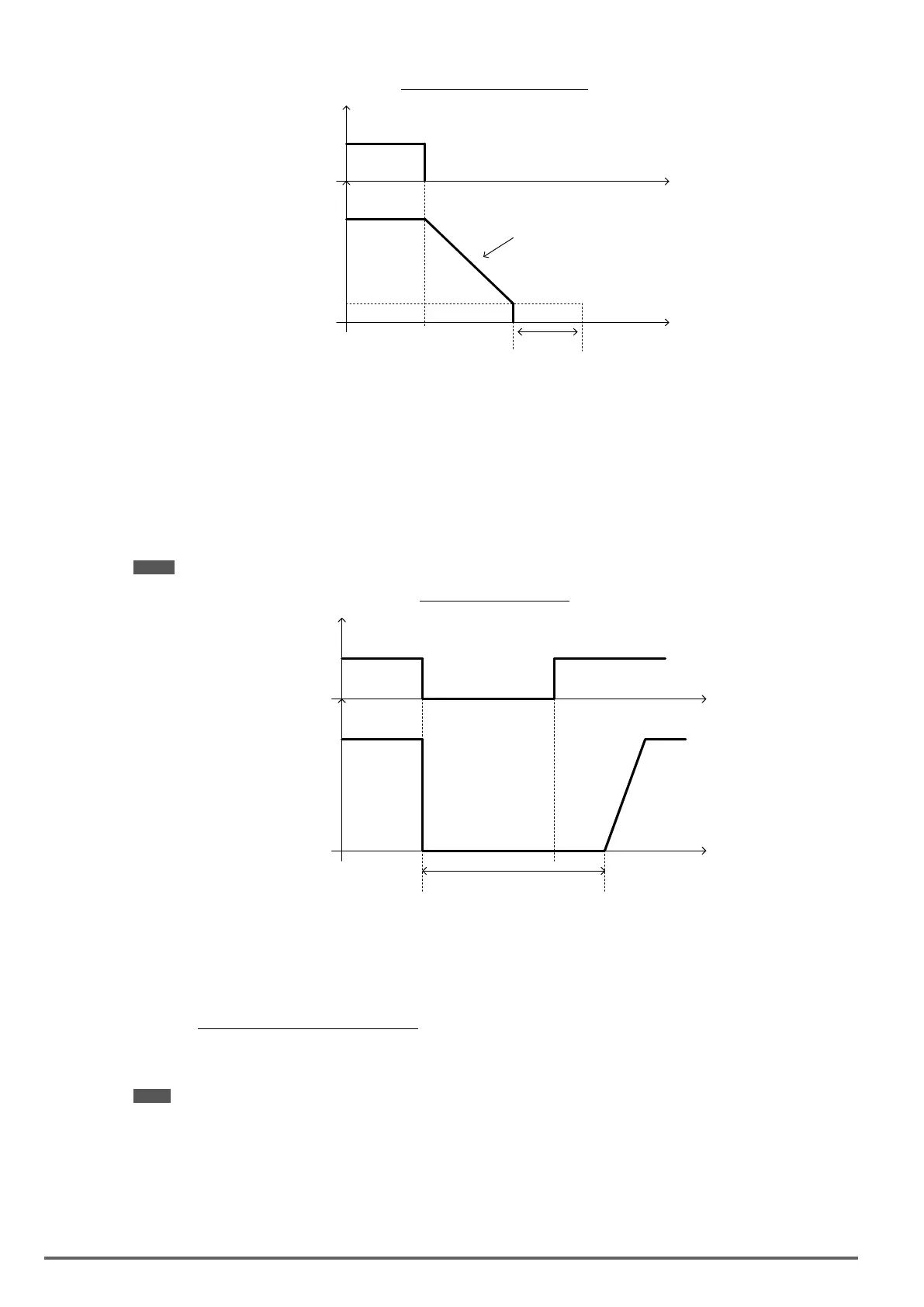
07-09=1: Coast to stop
When a stop command is issued, the motor will coast to a stop. Stop time depends on motor load and friction
of the system.
The inverter waits for the time set in the minimum baseblock time (07-18) before accepting the next run com-
mand.
In SLV mode (00-00=2) the speed search function is automatically enabled upon the next run command.
Note: When using a mechanical brake set parameter 07-26 to 1 (Software version 1.3 or later).
Figure4.4.59Coasttostop
Run
Stop
Run Command
Output
Frequency
Time
Time
Run
Minimum baseblock time (07-18)
t
b.b
07-09=2: DC braking to stop
When a stop command is issued, the inverter will turn off the output (Baseblock) and after the minimum Base-
block time (07-18) has expired activate DC braking (07-07). Refer to Figure 4.4.60.
The DC braking time (tDCDB) of Figure 4.4.60 is determined by the value of 07-08 (DC Braking start time) and
the output frequency at the time the stop command was issued.
tDCDB =
(07-08) x 10 x output frequency
Fmax (01-02)
Note: Increase the minimum Baseblock time (07-18) in case an Overcurrent trip occurs during the DC braking.
194 VDI100 • Instruction manual

 Loading...


