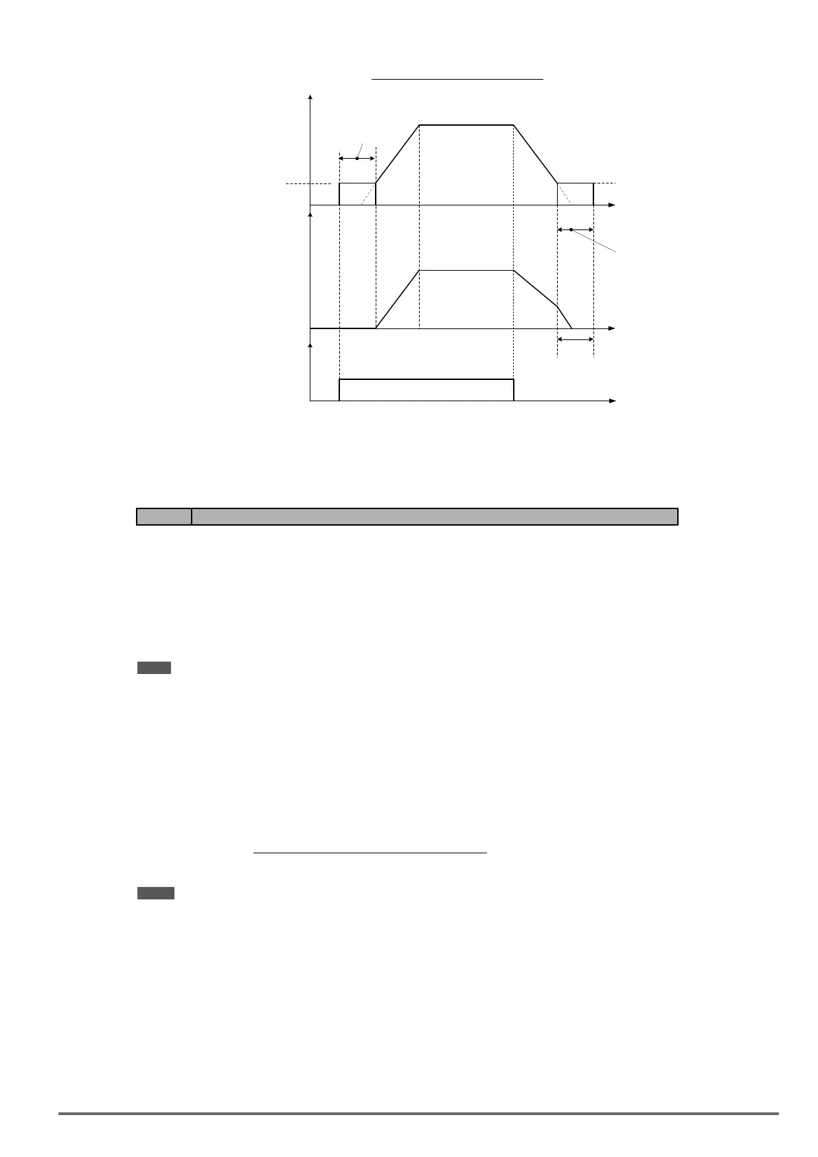
Figure4.4.57DCbrakingoperation
t
07-06
07-08
07-16
01-08
(Fmin)
Braking
time
The larger value of
01-08 or 07-06
Output
Frequency
Motor
Speed
Run
Command
t
t
DC braking operation can be controlled via any one of the multi-function input terminals (03-00 to 07) function
33. Refer to gure 4.4.57 for DC braking operation.
DC braking current can be controlled via the multi-function analog input (04-05) function 5. Refer to Figure
4.4.44.
Code Parameter Name / Range
07-09 Stop mode selection
0: Deceleration to stop
1: Coast to stop
2: DC braking to stop
3: Coast to stop with timer
When a stop command is issued the inverter stops according to the stop mode selected. There are four types
of stop modes,
Note: DC braking stop (2) and coast to stop with timer (2) are not available in SV mode.
07-09=0: Deceleration to stop
When a stop command is issued, the motor will decelerate to the minimum output frequency (01-08) Fmin and
then stop. Deceleration rate depends on the deceleration time (factory default: 00-15).
When the output frequency reaches the DC braking stop frequency (07-06) or the minimum output frequency
(01-08), DC injection braking is activated and the motor stops.
Deceleration time =
Output frequency when stop command is issued
× deceleration time setting
Maximum output frequency Fmax (01-02)
Note: S curve setting will add to the overall stop time
VDI100 • Instruction manual 193

 Loading...


