Stall prevention level during acceleration (Constant horsepower)
Stall Prev. Lev. Acceleration (CH) =
Stall prevention level in acceleration (08-01) x Fbase (01-12)
Output frequency
Parameter 08-21 is the stall prevention limit value in Constant Horsepower region. Refer to gure 4.4.68.
Figure4.4.68Stallpreventionlevelandlimitinacceleration
Constant Torque
region
Constant Horsepower
region
08-01
08-21
Output
frequency
Stall
prevention
level during
acceleration
Motor2 Acceleration Stall Prevention Level (08-40) and Motor2 Acceleration Stall Prevention Limit (08-41) are
Used when 03-00~03-07=40 (Switching between Motor 1/Motor 2)
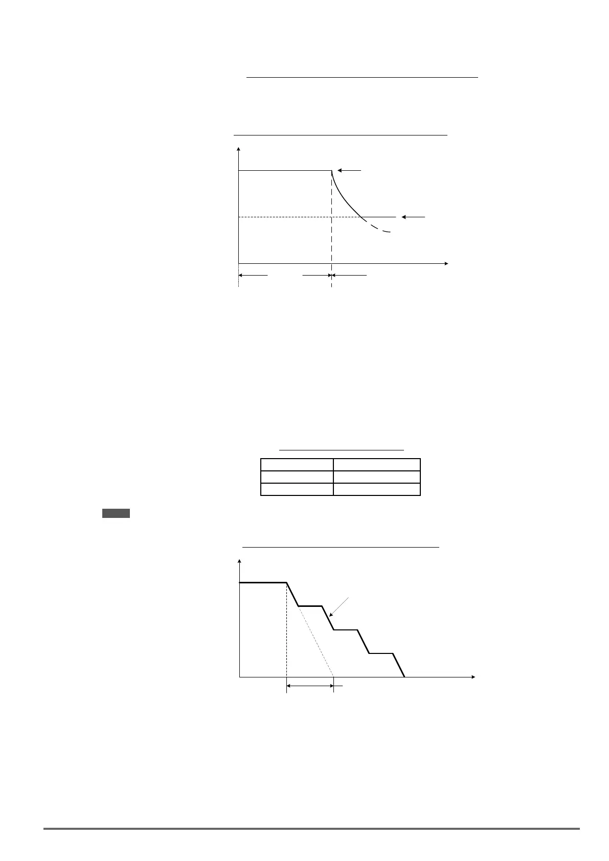
Stallpreventionselectionduringdeceleration(08-00=xx0xb)
Stall prevention during deceleration automatically increases the deceleration time according based on the
DC-bus voltage to prevent over-voltage during deceleration. Refer to Figure 4.4.69 for stall prevention during
deceleration
When the DC-bus voltage exceeds the stall prevention level deceleration will stop and the inverter will wait for
the DC-bus voltage to fall below the stall prevention level before continuing deceleration. Stall prevention level
can be set by 08-02, see Table 4.4.13.
Table4.4.13Stallpreventionlevel
Inverter model 08-02 default value
230V class 385VDC
400V class 770VDC
Note: When using external braking (braking resistor or braking module) disable stall prevention during deceleration (08-
00 to xx1xb).
Figure4.4.69Stallpreventionselectionindeceleration
t
Output
frequency
Deceleration time is extended to
prevent overvoltage.
Deceleration
time
Stall prevention selection during run (08-00=x0xxb)
Stall prevention during run can only be used in V/f or V/f + PG and SLV2control mode.
This function prevents the motor from stalling by automatically reducing the output frequency during run.
If the inverter output current rises above the level set in parameter 08-03 for the time specied in parameter 08-
22, the inverter output frequency is automatically decreased following deceleration time 1 (00-15) or decelera-
tion time 2 (00-17).
When the inverter output current falls below the level set in parameter (08-03) minus 2%, normal operation con-
tinues and the output frequency increases to the frequency reference using the acceleration time 1 or accelera-
VDI100 • Instruction manual 203

 Loading...


