feedback loss warning message “Pb” will be displayed on the keypad and the inverter will continue to operate.
10-11=2: Fault
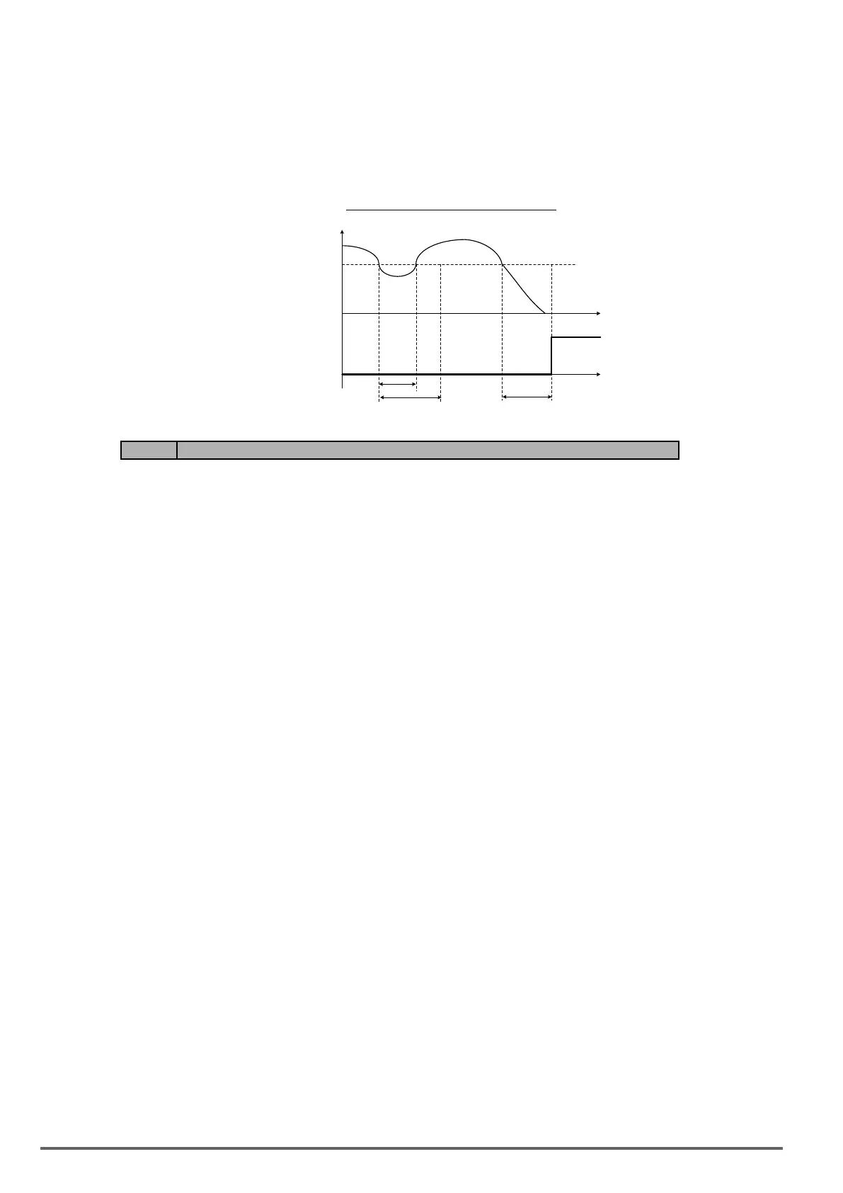
A feedback loss condition is detected when the PID feedback value falls below the value set in parameter 10-
12 (PID feedback loss detection level) for the time set in parameter 10-13 (PID feedback loss detection time).
PID feedback loss fault message “Pb” will be displayed on the keypad, the inverter stops and the fault contact
is activated.
Figure4.4.82PIDfeedbacklossdetection
t
10-13
t1
10-13
FBL
Detection
10-12
Feedback
Value
t
Code Parameter Name / Range
10-17 Start frequency of PID sleep
0.00~599.00 Hz
10-18 Delay time of PID sleep
0.0~255.5 s
10-19 Frequency of PID wakeup
0.00~599.00 Hz
10-20 Delay time of PID wakeup
0.0~255.5 s
10-29 PID sleep selection
0: Disable
1: Enable
2: Set by DI
10-40 Selection of PID Sleep Compensation Frequency
0: Disable
1: Enable
The PID Sleep function is used to stop the inverter when the PID output falls below the PID sleep level (10-17)
for the time specied in the PID sleep delay time parameter (10-18).
The inverter wakes up from a sleep condition when the PID output (Reference frequency) rises above the PID
wake-up frequency (10-19) for the time specied in the PID wake-up delay time (10-20).
Use parameter 10-29 to enable / disable PID sleep function.
10-29 =0: PID Sleep function is disabled.
10-29 =1: PID sleep operation is based on parameters of 10-17 and 10-18.
10-29 =2: PID sleep mode is enabled by multi-function digital input
Refer to gure 4.4.83 (a) and (b) for PID sleep / wakeup operation.
220 VDI100 • Instruction manual
 Loading...


