EasyManua.ls Logo

gefran VDI100 Series User Manual

gefran VDI100 Series
362 pages
To Next Page IconTo Next Page
To Previous Page IconTo Previous Page
Page #239 background imageLoading...
Page #239 background image
12 - Monitoring Parameters
Code Parameter Name / Range
12-00 Display screen selection (LED)
Highest
digit => 0 0 0 0 0 <= lowest digit
The value range of each digit is 0~7 from the highest to the lowest,
0: Default display (frequency&parameters)
1: Output current
2: Output voltage
3: DC bus voltage
4: Heatsink temperature
5: PID feedback
6: Analog Signal Input. (AVI)
7: Analog Signal Input. (ACI)
Note: The highest bit is used for power-up monitor. The 4 least significant bits can be used to customize the display se-
quence see chapter 4.1.3.
Code Parameter Name / Range
12-01 PID feedback display mode (LED)
0: Display the feedback value in integer (xxx)
1: Display the feedback value with one place after the decimal point (xx.x)
2: Display the feedback value (x.xx) with two places after the decimal point
12-02 PID feedback display unit setting (LED)
0: xxxxx (no unit)
1: xxxPb (pressure)
2: xxxFL (flow)
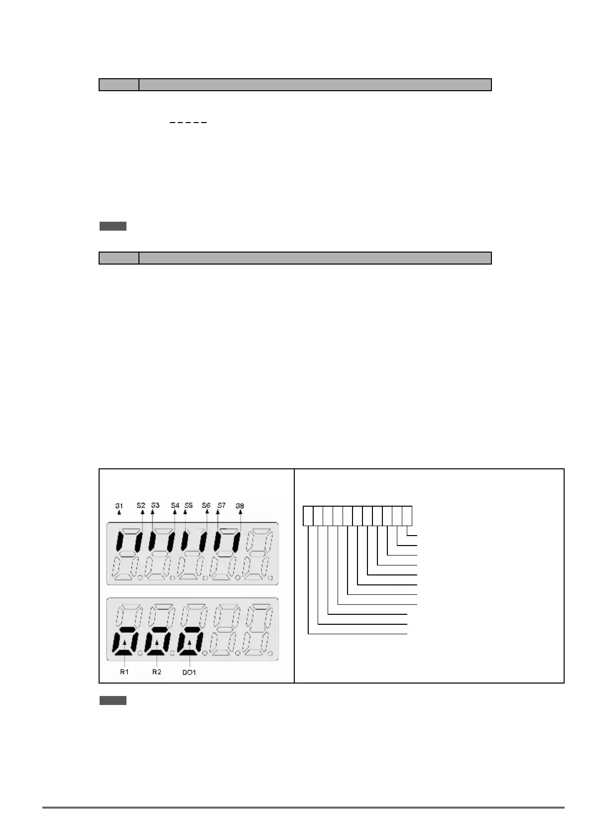
12-05 Status display of digital input terminal (LED / LCD)
Read-only
Terminals S1-S8 are represented using two segments of each digit. Segment turns on when input is active.
The bottom segments of each of the rst three digits are used to represent the digital outputs (R1, R2, DO1).
Segments turn on when output is active.
Example1:
S1~S8, R1, R2 and DO1 are ON
Example 2:
S1~S8, R1, R2 and DO1 are OFF
00 00 00 0 0
Input Terminal(S8)
Input Terminal(S7)
Input Terminal(S6)
Input Terminal(S5)
Input Terminal(S4)
Input Terminal(S3)
Input Terminal(S2)
Input Terminal(S1)
0: OPEN
1: CLOSE
000
Output Terminal(DO1)
Output Terminal(R2)
Output Terminal(R1)
Note: Refer to section 4.3 for monitors 12-11~12-64.
Monitoring parameter 12-66: Encoder Angle
Encoder PG pulse (20-27) is set to correct connection with the encoder wiring. Make the motor rotate forwardly
at non-run state and the angle will accumulate to 360°at two times; if make the motor rotate reversely, the angle
will regress to 360° at two times.
Monitoring parameter 12-67: Cumulative Energy (kWHr) & 12-68: Cumulative Energy (MWHr)
VDI100 • Instruction manual 239

Table of Contents

Questions and Answers:

gefran VDI100 Series Specifications

General IconGeneral
Brandgefran
ModelVDI100 Series
CategoryInverter
LanguageEnglish

Summary

1. Safety Precautions

1.2. Before Supplying Power to the Inverter

Ensures correct wiring and warns against connecting input supply to output terminals.

1.3. Wiring / Câblage

Details proper grounding, RCD compliance, and dielectric withstand test precautions.

1.4. Before Operation

Covers model matching, carrier frequency adjustment for long cables, and cover installation.

1.6. Operation / Opération

Provides guidelines for safe inverter operation, including cover installation, motor connection, and fan operation.

1.7. Maintenance, Inspection and Replacement

Details procedures for maintenance, inspection, and replacement, emphasizing safety precautions.

2. Model Description

2.1. Nameplate Data

Essential for verifying inverter nameplate and ensuring correct rating for application.

2.2. Inverter Models – Motor Power Rating (HD – Heavy Duty)

Lists inverter models and their corresponding applied motor power ratings for Heavy Duty applications.

3. Environment and Installation

3.1. Environment

Specifies operating temperature, storage, humidity, altitude, installation site, and shock conditions.

3.2. Installation

Details inverter installation in an upright position and required surrounding space for heat dissipation.

3.3. External View

Illustrates the external appearance of different inverter sizes, labeling key components.

3.4. Warning Labels

Highlights important warning information located on the front cover that must be read upon installation.

3.5. Removing the Front Cover and Keypad

Explains how to remove the front cover to access terminals for wiring connections.

3.6. Wire Gauges and Tightening Torque

Provides UL approved wire gauges, crimp terminals, and fastening torque specifications.

3.8. General Wiring Diagram

Illustrates the basic power and control circuit terminal connections for the inverter.

3.10. Power Terminals

Specifies terminal connections for input power, inverter output, and ground.

3.12. Inverter Wiring

Provides wiring precautions, power input terminal details, and grounding requirements.

4. Keypad and Programming Functions

4.1. LED Keypad (KB-LED-VDI100)

Details the LED keypad display, its keys, and their functions for inverter operation and parameter setting.

4.2. LCD Keypad (KB-LCD-VDI100)

Explains the LCD keypad display, its keys, and the menu structure for programming and monitoring.

4.3. Parameters

Provides a comprehensive list of all inverter parameters categorized into groups for easy access and configuration.

Related product manuals