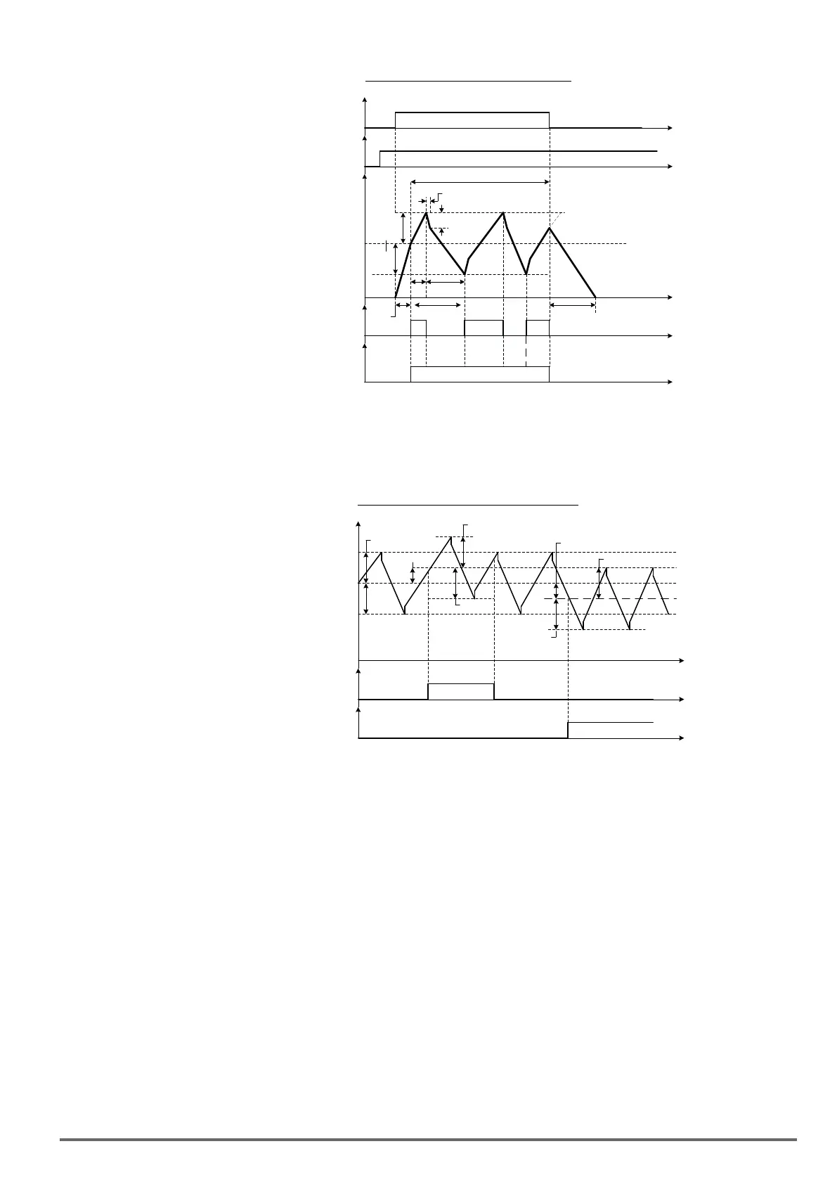
Figure4.4.105ON/OFFcontrolofwobble
Run
Command
t
up
t
down
19-02
19-01
19-01
Traverse Run
(03-00 –07 =37)
Output frequency
19-00
t
t
t
t
t
19-04
t
accel
t
decel
Traverse operation
19-03
Traverse Up
(03-11 to 03-12 = 28)
During Traverse
(03-11 to 03-12 = 29)
In wobble operation, the center frequency can be controlled by one of multi-function digital inputs.
The wobble upper and lower deviation command (03-00 to 07 = 38) and the wobble lower deviation command
(03-00 to 07 = 39) cannot be active at the same time, this will result in the inverter operating at the original
center frequency (19 - 00). Refer to Figure 4.4.106.
Figure4.4.106Upper/Loweroffsetoperation
19-07
19-01
19-01
Output frequency
19-00
t
t
t
Upper Deviation
Command
(03-00 to 03-07 = 38
19-01
19-06
19-01
19-01
19-01
Lower Deviation
Command
(03-00 to 03-07 = 39
The wobble operation can be used during acceleration and deceleration when the stall prevention function is
idle.
Select the appropriate inverter size to match the system requirement.
The wobble operation frequency range is determined by the upper limit and lower limit of the inverter frequency.
If (center frequency + amplitude) is greater than the upper frequency limit, the output frequency is limited to the
upper frequency limit; if (center frequency - Amplitude) is less than the lower frequency limit the output frequen-
cy is limited to the lower frequency limit.
VDI100 • Instruction manual 261

 Loading...


