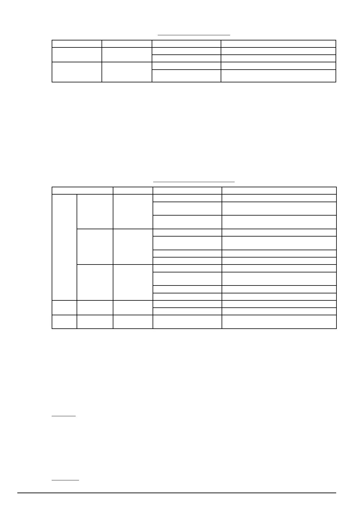
Table4.4.16Torqueinputmethod
Input Input terminal Parameter setting Description
Voltage input
(0 -10V)
AI2
(SW1-2=” V ”)
04-00=0,2 Terminal AI2 signal level: 0 - 10V
04-05=15 AI2 used as for torque reference
Current input
(4 - 20mA)
AI2
(SW1-2=” I ”)
04-00=1,3 Terminal AI2 signal level: 4 - 20mA
04-05=15 AI2 used as for torque reference
21-01: Torque lter time
Time constant used to reduce the torque signal interference and adjust the torque response. Increase lter time
in case the system becomes unstable.
21-02/21-03: Speed limit input setting
Limits the motor speed while operating in torque control. When the external torque reference and the system
load are out of balance the speed limit may be used to prevent the motor from damaging the system.
The speed limit can be set via the digital inputs or using and analog input signal to set the speed limit level.
Refer to the table 4.4.17 for the speed limit input method.
Table4.4.17Speedlimitinputmethod
Input method Input terminal Related parameter setting Description
1
Voltage input
(-10V – 10V)
AI1
21-02=0 Analog input (AI1 or AI2) as speed limit
00-05=1
Analog input (AI1 or AI2 is set by 04-05 ) as reference
frequency input
04-00=2,3
Terminal AI1 signal level : -10V - 10V
(if the speed limit is plus value, set 04-00=0, 1)
Voltage input
(10V - 10V)
AI2
(SW2=” V ”)
21-02=0 Analog input (AI1 or AI2) as speed limit
00-05=1
Analog input (AI1 or AI2 is set by 04-05 ) as reference
frequency input
04-00=0,2 Terminal AI2 signal level : 0V - 10V
04-05=12 AI2 will be added to terminal AI1 as speed limit value
Current input
(4 - 20mA)
AI2
(SW2=” I ”)
21-02=0 Analog input (AI1 or AI2) as speed limit
00-05=1
Analog input (AI1 or AI2 is set by 04-05 ) as reference
frequency input
04-00=1,3 Terminal AI2 signal level : 4 – 20mA
04-05=12 AI2will be added to terminal AI1 as speed limit value
2
Parameter 21-03
setting
-
21-02=1 Set the speed limit to be controlled by 21-03
21-03 Set speed limit
3
Communication
Input (2502H)
S+ & S- 21-02=2 Communication is used to be the speed limit.
The rotation direction in speed control depends on the speed limit signal:
• Positive voltage: Forward, speed limit (21-03 + 21-04).
• Reverse speed limit is zero or reversal direction (-21-04).
• Negative voltage: Reverse, speed limit (-21-03-21-04).
• Forward, speed limit is zero or forward direction (21-04).
If the speed limit bias is set to 0, the motor speed will be limited to 0 when the rotation direction of the motor
and the speed limit are in reverse.
Example: The speed limit analog signal is a positive voltage and the motor is in forward operation, then the
effective speed range in torque control is from 0 to the analog speed limit value.
21-04: Speed limit bias setting
Speed limit bias (21-04) is used to adjust the boundaries of the speed limit. The speed limit bias (21-04) can be
used to set the same limit value in forward and reversal direction and is set as a percentage of the maximum
output frequency (01-02).
Example 1: Set 30% speed limit in forward and reverse direction.
272 VDI100 • Instruction manual

 Loading...


