[C3]
C3
0020
M2
I3
0000
I1
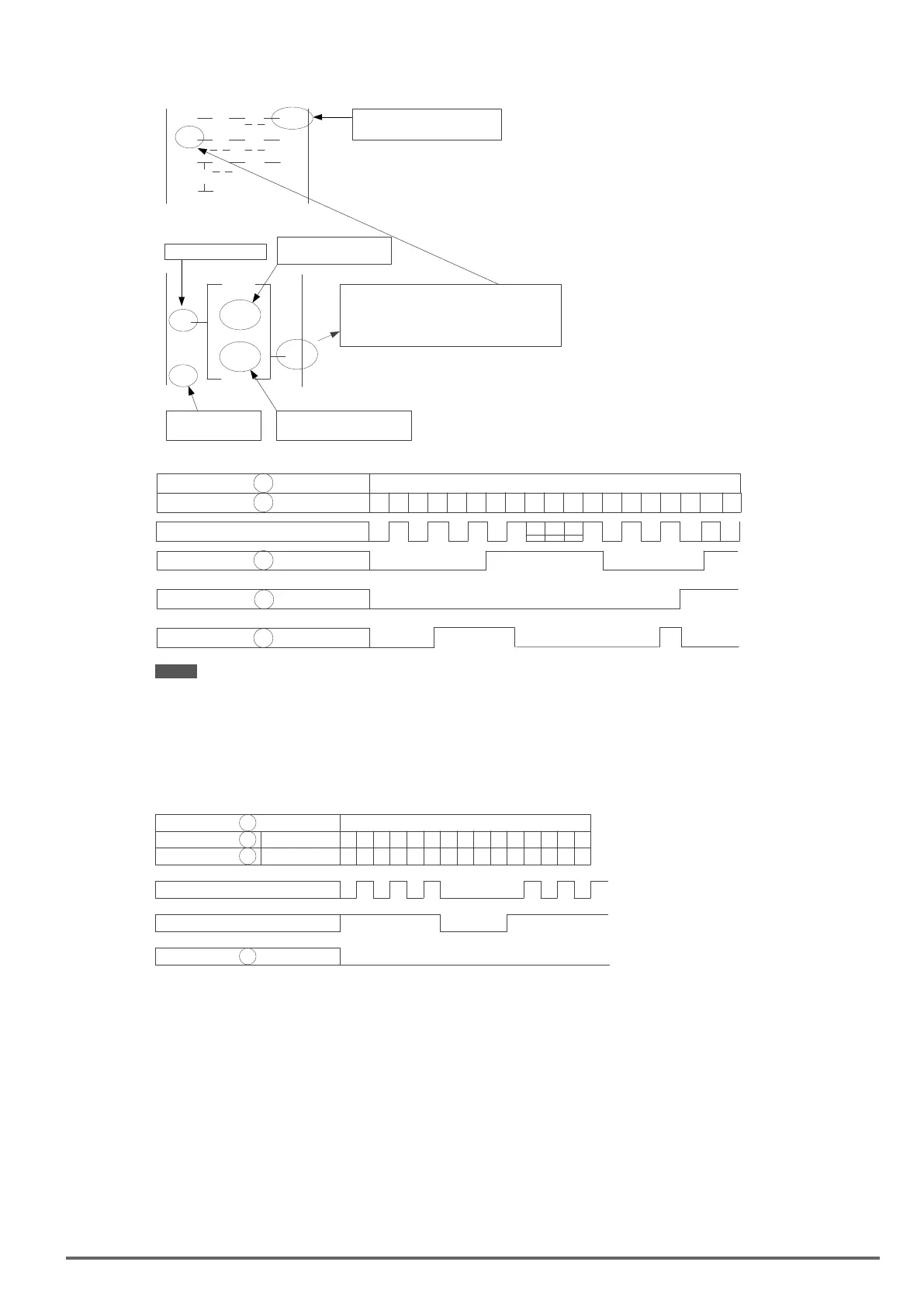
C3 input pulse counter is
determined by I1 and i2.
C3
C3 turns ON when the counter value
reaches the set Value and at the same
time, the C3 input in the ladder program
turns ON as well.
Input from the function program
Input from ladder program
I3 ON reset
Counter value
Counter compare value
Up/down counting
Internal
Counter Value
i2
[Q1]
q1 [M2]
m1
M2
Counter mode 2
5
20
6
4
19 19 20 20 18 18 19 19
0
21
21
20
20 19 20
0 20
20
Counter input pulse
2
3
OFF
ON
ON
OFF
OFF
ON
ON
OFF
ON
20
Note: In this mode the internal counter may increase past the counter compare value, unlike mode 1 where the internal
counter value is limited to the counter compare value.
(1) Counter mode 3 is similar to the counter mode 1, with the exception that the counter value is saved when
the drive is powered down and reloaded at power up.
(2) Counter mode 4 is similar to the counter mode 2, with the exception that the counter value is saved when
the drive is powered down and reloaded at power up.
5
4
1 1 2 2 3 4 4 5 5
20
Counter input pulse
Power switch
6
3Mode 3 & 4
4
1 1 2 2 1 1 2 20Mode 1 & 2
VDI100 • Instruction manual 289

 Loading...


