Default Communication Setting is: Address “1”, 9600 Bits/sec, 1 Start Bit, 1 Stop Bit, and No Parity
The serial communication link function uses RS485 Modbus RTU protocol and allows for:
1) Monitoring (data monitoring, function data check).
2) Frequency setting.
3) Operation command (FWD, REV, and other commands for digital input).
4) Write function data.
Frequency Reference Command Register
Inverter Frequency Reference Register: 2502 (Hexadecimal) - Bit 0 – Bit 15: 0.00 ~ 400.00 Hz
Examples:
FrequencyReferenceCommand:10.00Hz(InverterNodeAddress:01)
Command String (hexadecimal): 01 06 25 02 03 E8 23 B8
To set the frequency reference to 10.00, a value of ‘1000’ (03E8h) has to be send to the inverter.
FrequencyReferenceCommand:30.00Hz(InverterNodeAddress:01)
Command String (hexadecimal): 01 06 25 02 0B B8 24 44
To set the frequency reference to 30.00, a value of ‘3000’ (0BB8h) has to be send to the inverter.
FrequencyReferenceCommand:60.00Hz(InverterNodeAddress:01)
Command String (hexadecimal): 01 06 25 02 17 70 2D 12
To set the frequency reference to 60.00, a value of ‘6000’ (1770h) has to be send to the inverter
Note: The last 2 bytes of the command strings consist of a CRC16 checksum, please refer to section 4.5 of the instruction manual for
additional information.
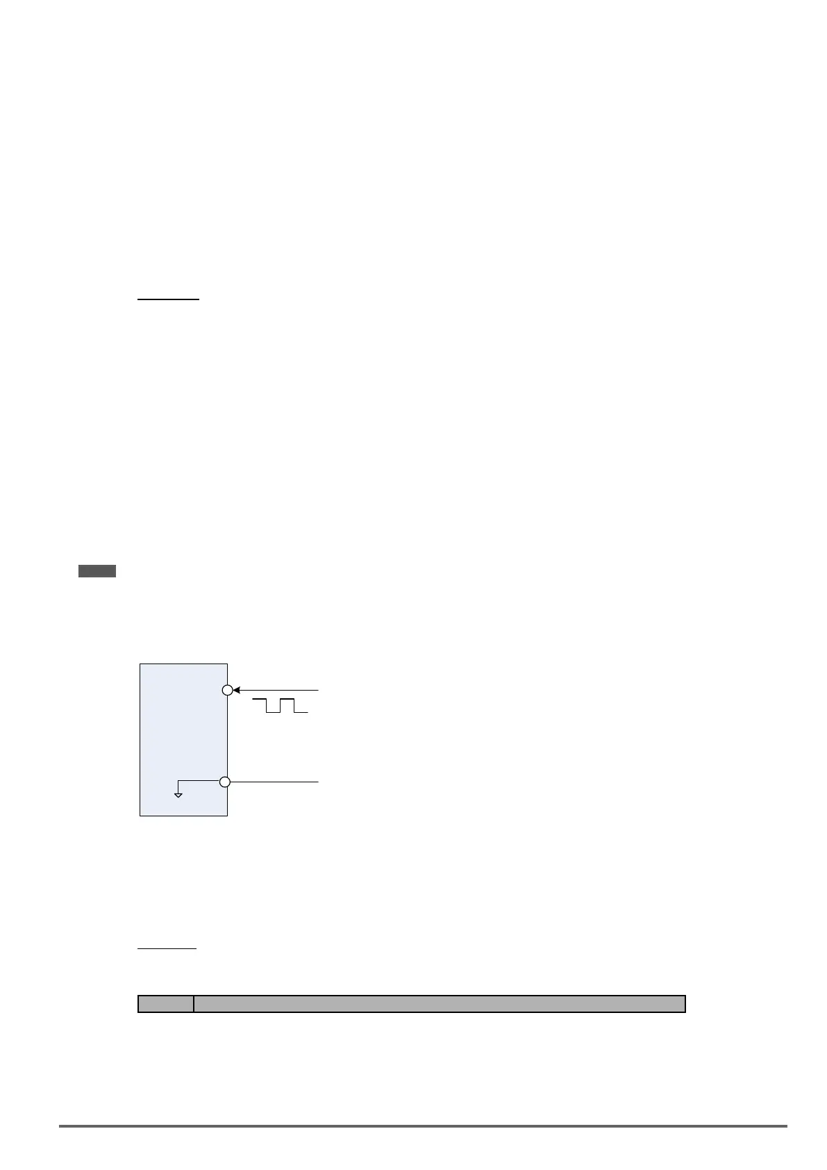
6.4. ReferencefromPulseInput(00-05=4)
PI
GND
0V
(Internal resistence : 3.89 K)
Serial pulse input
Specification
Low Input Level: 0.0 to 0.5 V
High Input Level: 4.0 to 13.5 V
Duty cycle: (ON / OFF) 30 % to 70%
Pulse Input frequency range: 50 to 32 KHz
Set Pulse Input Setup as Frequency Reference
Set parameter 00-05 to 4 and 03-30 to 0 to use the pulse input terminal PI as the frequency reference source.
Next set the pulse input scaling (03-31), enter the pulse input frequency to match the maximum output frequen-
cy. Adjust the pulse input lter time in case interference or noise is encountered.
Example:
Pulse train input maximum 10 kHz, set parameter 03-31 to 10000 when maximum frequency is set to 60.0Hz.
Code Parameter Name / Range
03-30 Selection of Pulse Input
0: General Pulse Input
1: PWM
Function selects source for the pulse input.
VDI100 • Instruction manual 313

 Loading...


