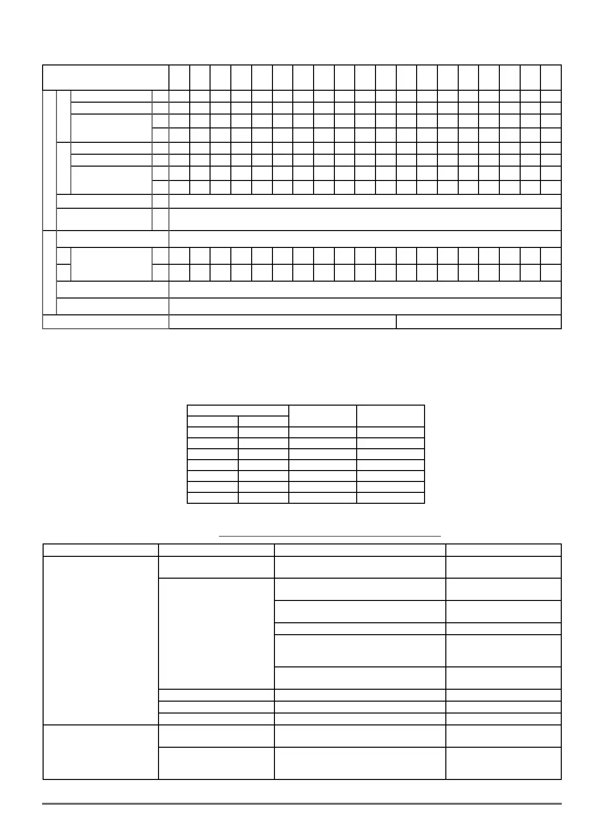
Three phase - 400V Class
Sizes VDI100
1007
1015
1022
2037
2055
3075
3110
3150
4150-F
4185
4220
5300
5370
5450
5550
6750
6900
71100
71320
71600
Output Rating
(2)
HD
(3)
Rated Output Capacity
kVA
2.6 3.2 4.2 7 11.3 13.7 18.3 23.6 29.7 34.3 45.7 57.2 69.3 85.4 114 137 165 198 225
Rated Output Current
A
3.4 4.2 5.5 9.2 14.8 18 24 31 39 45 60 75 91 118 150 180 216 260 295
Maximum Applicable
Motor
(1)
HP
1 2 3 5 7.5 10 15 20 25 30 40 50 60 75 100 125 150 175 215
kW
0.75 1.5 2.2 3.7 5.5 7.5 11 15 18.5 22 30 37 45 55 75 90 110 132 160
ND
(4)
Rated Output Capacity
kVA
3.1 4.1 5.3 9.2 13.3 17.5 23.6 29.0 33.5 44.2 55.6 67.1 78.5 111 128 159 191 226 250
Rated Output Current
A
4.1 5.4 6.9 12.1 17.5 23 31 38 44 58 73 88 103 145 168 208 250 296 328
Maximum Applicable
Motor
(1)
HP
2 3 5 7.5 10 15 20 25 30 40 50 60 75 100 125 150 175 210 250
kW
1.5 2.2 3.7 5.5 7.5 11 15 18.5 22 30 37 45 55 75 90 110 132 160 185
Maximum Output Voltage
V
Three-Phase, 380V to 480V
Maximum Output
Frequency
Hz
0.1~599 (Based on parameter setting)
Input Power
Rated Voltage, Frequency Three-Phase, 380V to 480V, 50/60Hz
HD
Rated Input Current
A
3.7 5.3 6.0 9.6 15.5 18.7 25.0 33.7 42.4 48.9 65.2 81.5 98.9 130 159 181 229 275 325
ND
A
4.5 5.9 7.5 11.6 18.2 24.0 32.3 41.3 47.8 58.7 78.3 95.7 112 159 181 229 275 325 361
Allowable Voltage Fluctuation -15% ~ +10%
Allowable Frequency Fluctuation ±5%
Braking Transistor Built-in Option (External Braking Module)
(1) Based on the standard 4-pole induction motor. The selected inverter must have a higher output current rating than the motor.
(2) The default setting of VDI100 is HD (heavy duty mode). To switch VDI100 to ND (normal duty mode) set parameter (00-27) to 1. When switching to ND (normal duty mode),
the frequency will change to 2kHz.
(3) The default setting of carrier frequency in HD mode is shown into the table below, if the setting value is higher than default setting, derating may be required.
(4) The default setting of carrier frequency in ND mode is 2kHz, if the setting value is higher than default setting, de-rating may be required.
(5) If control mode is set to SLV mode (*) and maximum frequency is larger than 80Hz, the carrier frequency range is 2~8kHz.
(6) Option (External Braking Module)
Inverter Voltage and Power HD mode carrier freq
range
HD mode carrier
freq default setting
230V Class 400V Class
0.75 ~ 15 kW 0.75 ~ 22 kW 2~16 kHz 8 kHz
18.5 kW - 2~12 kHz 6 kHz
22 kW - 2~12 kHz
(5)
5 kHz
- 30 ~ 37 kW 2~12 kHz
(5)
5 kHz
- 45 ~ 132 kW 2~10 kHz
(5)
5 kHz
- 90 kW 2~10 kHz 4 kHz
- 160 kW 2~8 kHz 3 kHz
The following table shows maximum output frequency for each control mode.
Table3.18.1:Maximumoutputfrequencyforeachcontrolmode
Duty Cycle Control mode (*) Other settings Maximum output frequency
Heavy Duty
(00-27=0)
V/f
V/f + PG, SLV2
maximum frequency set to 599Hz 599Hz
SLV
230V Class: 0.75~7.5 kW,
400V Class: 0.75~11 kW
150Hz
230V Class: 11~18.5 kW,
400V Class: 15 kW
110Hz
400V Class: 18.5 ~ 22 kW 100Hz
230V Class: 22 kW,
400V Class: 30~160kW carrier (11-01) is set as 8K
or below 8K
100Hz
230V Class: 22 kW,
400V Class: 30~132kW carrier (11-01) is above 8K
80Hz
SV
Full range 400Hz
PMSV
Full range Twice of Base frequency
PMSLV
Full range Base frequency
Normal Duty
(00-27=1)
V/f
V/f + PG
maximum frequency set to 599Hz 599Hz
SLV /SV
PMSV/ PMSLV
SLV2
No normal duty mode
(*) See PAR 00-00 Control mode selection (ch. “4.4. Description of Parameters” on page 95).
VDI100 • Instruction manual 35

 Loading...


