A1.2ProbusDPNetwork
This section shows a Probus DP network consisting of several inverters communicating using the probus DB
option card.
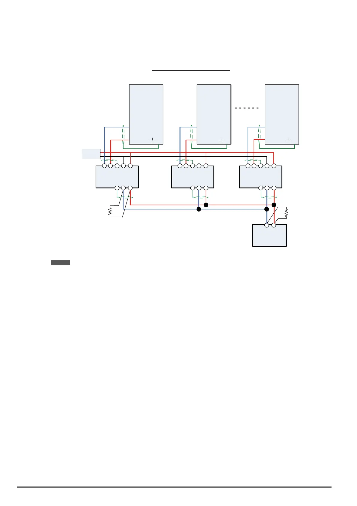
WiringdiagramProbusDPNetwork
S-
Inverter #1
S+
S-
Inverter #2
S+
S-
Inverter #n
S+
Profibus
Controller
Resistor
220 Ohm
Resistor
220 Ohm
E E
5 4 3 2 1
TB1
5 4 3 2 1
TB1
5 4 3 2 1
TB1
3 2 1 3 2 1 3 2 1
TB2 TB2 TB2
+-
+-
+-
+
-
24V
EXP-PDP-BDI/VDI
EXP-PDP-BDI/VDI EXP-PDP-BDI/VDI
Notes:
- Requires a Probus DP option card (EXP-PDP-BDI/VDI) for each inverter.
- Requires 24Vdc power supply. Size power supply based on the number of inverters on the network.
- A maximum of 31 inverters can be connected to the network. Terminating resistors of 220 ohm must be
installed at both end of the network.
Refer to
EXP-PDP-BDI/VDI option communication manual for more information.
352 VDI100 • Instruction manual

 Loading...


