13
X1 - Mains supply / supply of external devices
Mains supply of the door control.
Note the chapter "Electrical installation / mains supply".
i
Supply of external devices
External devices can only be supplied with power over terminals X1/1.8 and X1/1.9 when the door control is
connected symmetrically to supply networks with 3 N~ 400 V or 1 N~ 230 V.
Fuse protection by F1, micro fuse 1.6 A slow blow.
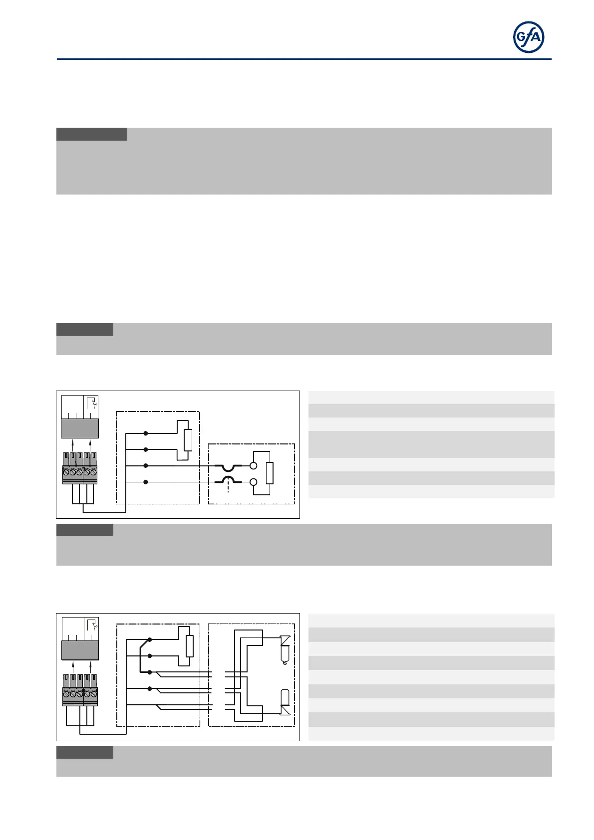
X2 - Safety devices
You can connect a safety edge or a light curtain to terminals X2.1 to X2.5.
Mount the product according to the manufacturer's instructions.
Connect the safety devices to the door control using a spiral cable or a WSD door module. When using
spiral cables, we recommend routing the cable through the side of the door control box.
Follow the assembly instructions for the products.
i
In case of a defective safety edg
e, the door control switches to
Electrical safety edge
The input is designed for an electrical safety edge (NO) with a terminal resistance of 8k2 (+/- 5 % and 0.25 W).
2.1
2.3
2.5
2.2
2.4
X2
1
2
3
4
ST+
ST
SK1
SK2
A18
B1
8K 2
5k0
R1
1234
Input for door safety switch
Input for electrical safety edge
End of line resistor (8k2)
i
Following a short circuit of the electrical safety edge, fault indication
F 2.4
interrupted, fault indication
F 2.5
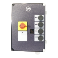
Optical safety edge
The input is intended for an infrared safety photocell with a transmitter and receiver in a rubber profile.
Pressing the rubber profile interrupts the light beam.
2.1
2.3
2.5
2.2
2.4
X2
1
2
3
4
ST+
ST
SK/b
SK/g
SK/w
A18
br
gn
w
B3
B2
5k0
1234
A18 Connection socket
ST+
Voltage supply (12 V)
ST Input for door safety switch
SK/b Mains supply (brown)
SK/g Output (green)
SK/w Ground (white)
B2 Optical transmitter
B3 Optical receiver
X2 Door control socket
i
When the optical safety edge is activated or damaged, fault indication
F 2.9