14
Pneumatic safety edge
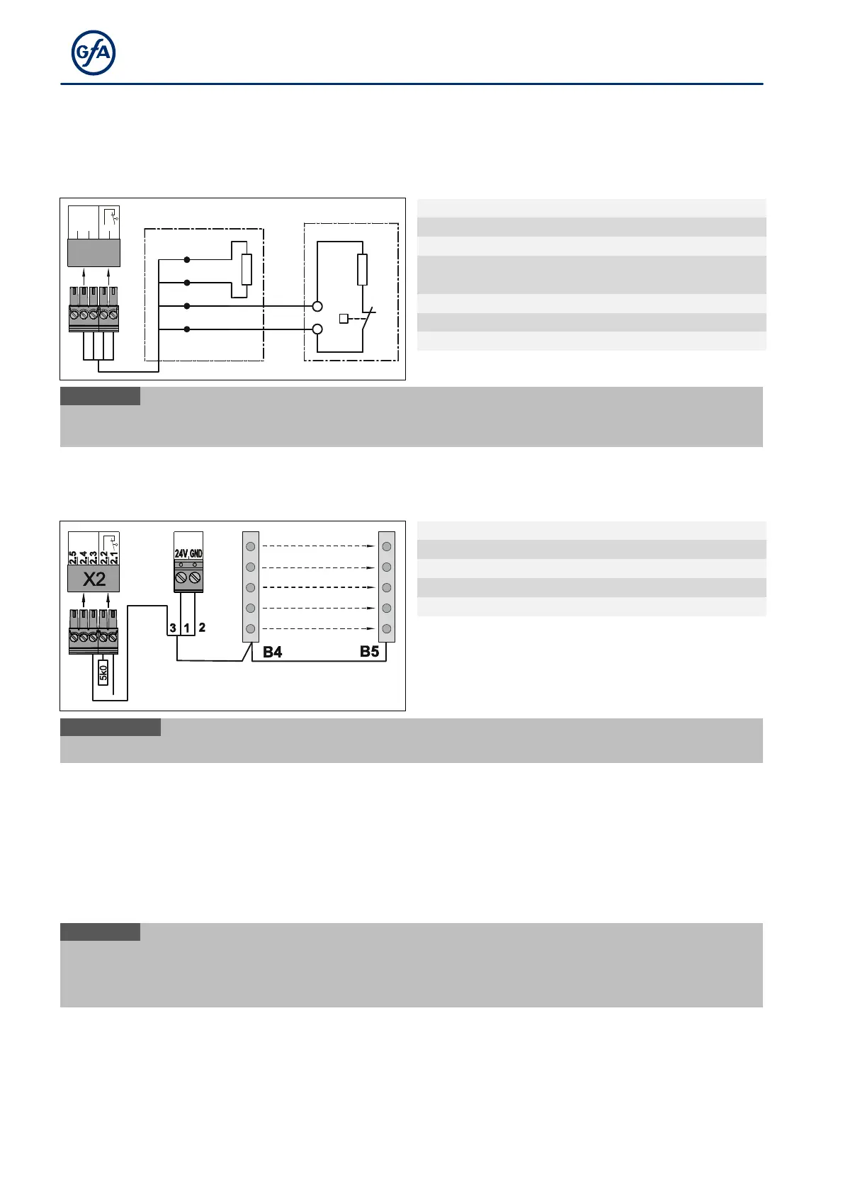
The input is designed for a pressure-wave switch system (NC) with a terminal resistance of
1k2 (+/-5 % and 0.25 W). The pressure wave switch system needs to be tested with final limit position CLOSE.
The test phase is initiated by pre-limit switch S5 (automatically for DES). If no switching signal is generated at
the pressure wave switch within 2 seconds, the test is negative and fault indication F 2.8 appears.
2.1
2.3
2.5
2.2
2.4
X2
DW
1K2
R2
1
2
3
4
ST+
ST
SK1
SK2
A18
5k0
1234
Input for pneumatic safety edge
End of line resistor (1k2)
i
When the pneumatic safety edge is activated or the current circuit is permanently interrupted, fault
indication F 2.6 appears. Fault indication
F 2.7
appears in case of a short circuit.
Light curtain (with an OSE interface only)
The input is intended for a light curtain with an OSE interface. The light curtain detects people and obstacles
without contact.
Signal output light curtain
Light curtain transmitter
i
When the beam of the light curtain is interrupted, fault indication
F 4.6
X2 - Door safety switch
You can connect a door safety switch for a pass door or slack-rope switch to terminals X2.1/2.2. The door
safety switches are connected to a safety circuit with Performance Level c (PLc) according to ISO 13849-1. The
safety circuit requires an overall terminal resistance of 5k0 for line cross-circuit monitoring.
Examples of door safety switches are shown below. Connect your product accordingly.
Mount the product according to the manufacturer's instructions.
i
When activated while the door is moving, the door stops and fault indication F 1.2 appears.
When the switch fails, fault indication F1.7 is displayed.
In the case of a line cross
circuit, fault indication
F1.8