7
Installation
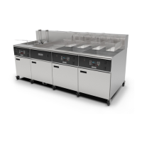
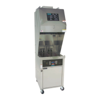
EOF 10-10/20
2-04. Electrical Connections
2-03. Electrical Requirements
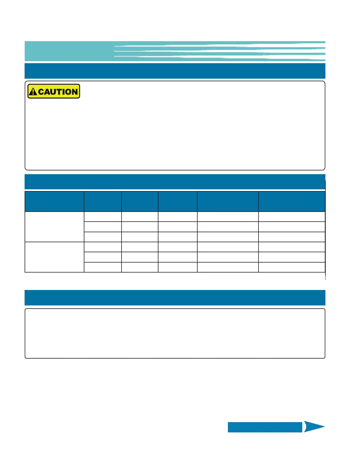
2-03.1. Electrical Specifications
Unit Voltage Phase kW Amp Draw
Curcuit Breaker Required
*EOF10-10
208 3 24 68 80
240 3 24 59 75
480 3 24 31 50
EOF-20
208 3 24 76 80
240 3 24 66 75
480 3 24 33 50
* EOF10-10 unit is a split vat fryer with a single power supply ... kW rating is total of the unit.
• Fryers must be properly grounded. Improper grounding may result in electrical shock to the user. Always refer
to local electrical code to ensure that proper grounding techniques are used for this or any other electrical equip-
ment. Always consult with a certified electrician, or other qualified service technician, to ensure that the electri-
cal circuit is of sufficient rating for supplying power to this appliance.
• Fryers are available from the factory wired for various voltage, phase and Hz, see Table below. To determine the
correct power supply for the appliance, check the serial label found on the rear panel of the Fryer, or inside the cab-
inet. Each unit of a banked battery requires a separate power service.
NOTE:
Each unit in the Fryer bank requires a separate power supply. Electrical installation materials (breakers, conduit,
fittings, wire, etc.) and installation labor shall be supplied by the customer. Work should be performed by a qual-
ified electrician, or service technician.
Installation must comply with local code requirements. Giles is not responsible for code compliance with regard
to installation and use of this appliance.
1. As needed, install appropriately sized Circuit Breakers in main breaker panel, see Table 2-03.1.
2. (Recommended) Install a disconnect switch box between main panel and Fryer.
3. Connect flexible conduit from the Disconnect to the Fryer unit. Allow enough conduit length so that the unit
can be moved away from the wall for cleaning and servicing, see Figure 2-04.1. Conduit to be routed along the
floor underneath the Fryer unit and turn up to a 90° conduit connector installed on the back of the Service Box.
4. Open Fryer unit Door and remove Service Box Cover, see Figure 2-04.1.
Continued on Next Page


 To Next Page