22
INSTALLATION | 333/334 HPLC PUMPS
ELECTRICAL CONNECTIONS
CONTACT CONNECTIONS
Make any single wire contact connections for input/output signals, which may be needed for
communicating with other equipment.
Contact Connections (Input & Output)
The input and output contact functions are shared between two terminal blocks (14-pin and
10-pin) situated on the pump’s rear panel.
The maximum input voltage for any electrical device connected to each input or output
contact is 48 V.
In order to connect signal wires to the terminal blocks, you must first fit the appropriate
connector (as supplied in the standard accessories package). The 14-pin connector fits the
left-hand socket and the 10-pin connector fits the right-hand socket. After gently pushing each
connectors into its socket, you can connect wires to the appropriate terminal.
To connect a wire to the terminal you should strip back the wire’s protective covering by 5 mm,
undo the terminal’s fixing screw, push the bared wire into the corresponding hole in the terminal
block, and then tighten the fixing screw using a small screwdriver.
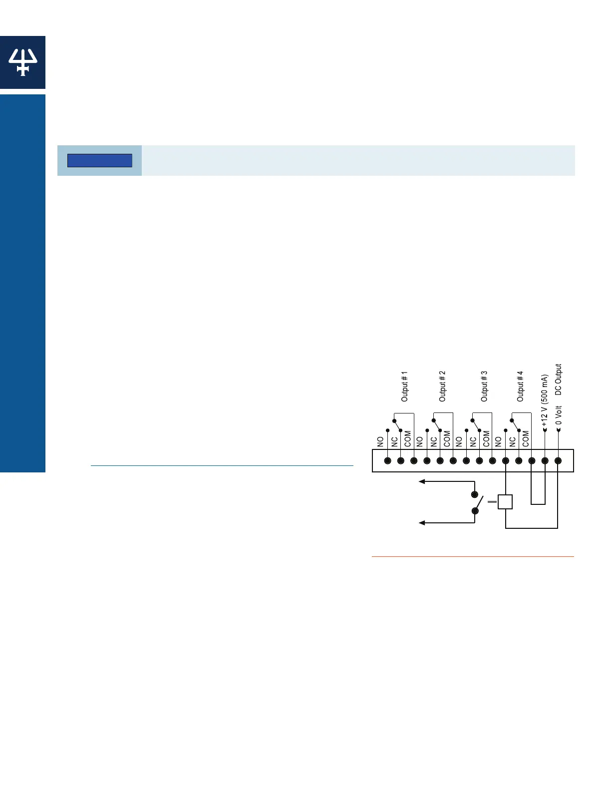
Powering an External Relay
A 12 V (500 mA) DC supply is available at the right-most pair of pins of the left-hand terminal.
This supply can be switched manually from the control panel or automatically from a Method
Program by connecting it to one of its neighboring outputs.
Output Signals
Four two-way relay-type outputs are available
via the left-hand socket. Each of these outputs is
electrically isolated from the others and from ground.
Switching from the ‘normally closed’ to the ‘normally
open’ position takes place under software control
(see Appendix D | Front Panel Control on page 67)
at pre-programmed times. You can program these
contacts to ‘Open’, ‘Close’, or ‘Pulse’, for a specific
duration.
You connect one wire from the receiving device to
the common terminal of Output # 1 (2, 3, or 4) and
a second wire to either the corresponding ‘normally
open’ or ‘normally closed’ terminal, depending on the
requirements of the receiving device.
An output (pin # 9) is available on the right-hand socket
for feeding a recorder or a PC (via a suitable interface). This output, which comes from the
pump’s microprocessor, can be configured to follow pressure, flow, or composition (%A, %B,
or %C). It is labeled ‘Digital’ but outputs a series of discrete signals (0–1 V) via the digital-to-
analog converter.
An output (pin # 10) is available on the right-hand socket for feeding any suitable recorder or
a PC (via a suitable interface). This analog output, which comes directly from the sensor, is for
pressure only (0.142–1 V for 0–60 MPa).
Figure 13
14-Pin (Output) Contact Connections
12 V Relay Coil
+
_
Power Contact