26
INSTALLATION | 333/334 HPLC PUMPS
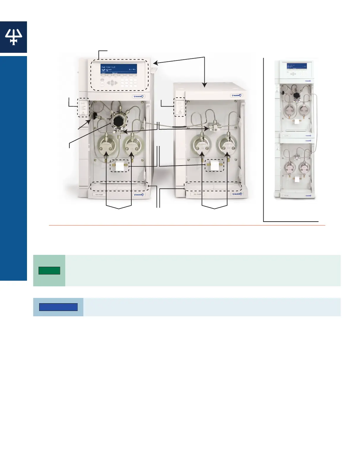
POSITIONING THE PUMPS
Positioning the Pumps
The 333/334 Pumps can be placed side-by-side or stacked to conserve bench space.
Standby
Panel
Reciprocating Piston
Standby
Panel
Outlet
Tees
Inlet
Tees
Drip Trays
Pressure
Purge &
Mixing
Module
(PPMM)
Reciprocating Piston
ilter
Stacked C
Figure 17
System Diagram for Paired 333/334 HPLC Pumps
(Side-by-Side Configuration on the Left; Stacked Configuration on the Right)
The tubing linking the two pumps goes through the tubing port, together with solvent and rinsing
port tubing. To make it easy to install and to remove tubing, there is a fissure in the tubing port,
which is accessed by rotating the tubing port until the fissure lines up with the opening in its housing.
Pre-shaped steel tubing is used to connect pumps. Do not bend or attempt to reshape this
tubing.