71333/334 HPLC PUMPS | USER’S GUIDE
FRONT PANEL CONTROL
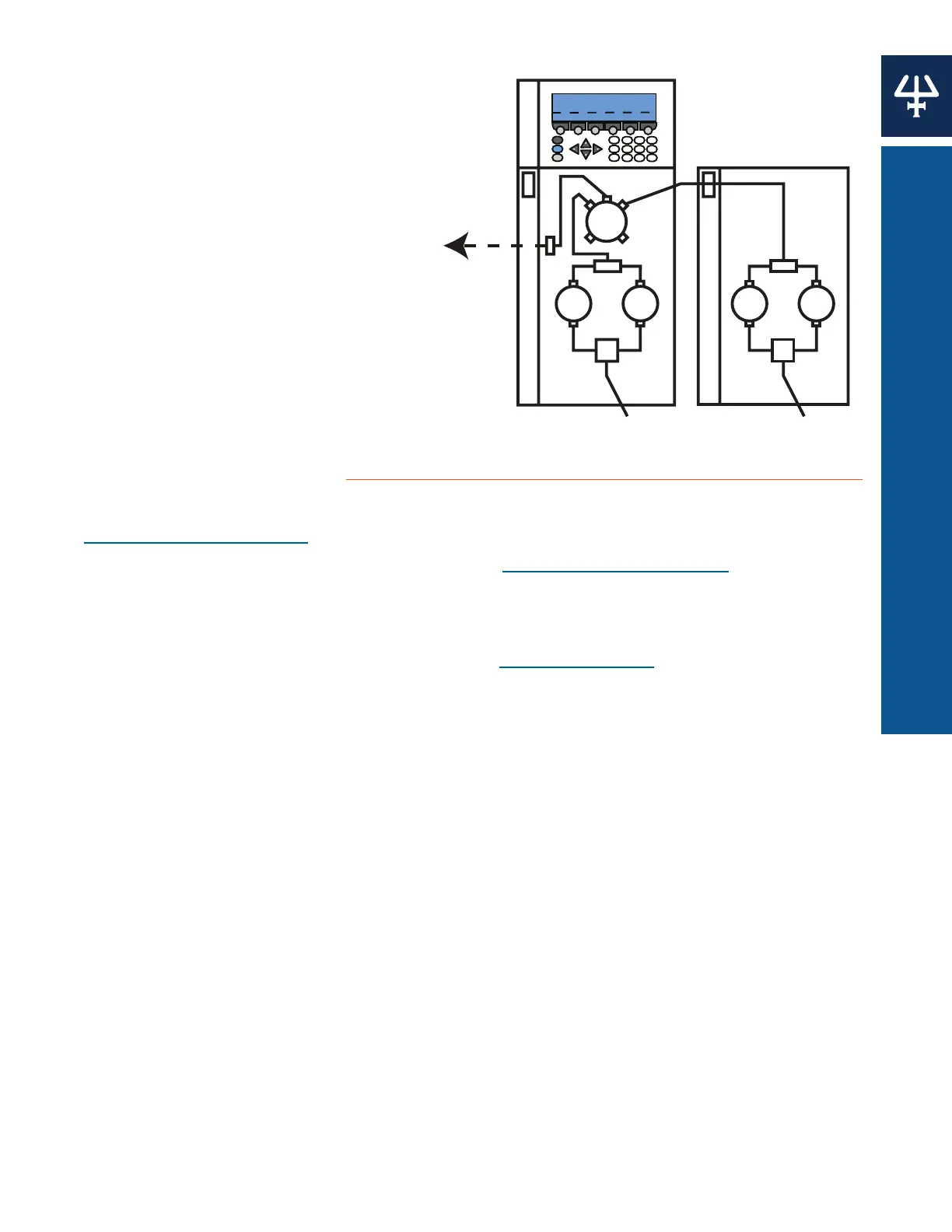
MAKING THE HYDRAULIC
CONNECTIONS TO AN
EXTERNAL INJECTOR
1. Connect from the outlet
filter of the 333 Pump to
the downstream injector.
2. Connect solvent line A to
the inlet tee piece on the
333 Pump.
3. Connect solvent line B to
the inlet tee piece on the
334 Pump.
4. Connect horizontal (part
number 380133592) or
vertical (part number
380132582) tubing from the
tee piece of the 334 Pump
to the inlet of the PPMM of
the 333 Pump.
5. Prime the system. See
Hydraulic Priming on page 78.
6. Initialize and run-in the piston seals (if new). See Run-In Procedure on page 52.
Software Setup
1. Switch on the pump(s). The initialization screen will appear briefly.
2. Check or set the GSIOC IDs for the devices. See GSIOC ID on page 21
3. Make the electrical connections between the instruments, including the GSIOC cable linking
the 333 Pump to controlled devices.
4. Check the software configuration. Makes changes as needed.
a. Press Edit > Config > Hard.
b. Make sure the correct device is selected before advancing to the next step. The
selected ID will blink. Use the Up and Down arrows to navigate.
c. Press Change at the Hardware Configuration screen.
d. Press Esc to leave the Hardware Configuration screen and advance to the
Configuration screen. The screen displays whether injection from pump is available, the
names of controlled devices, and the maximum number of solvents.
Alternatively, press Scan at the Hardware Configuration screen to identify any connected
pumps. Their configured IDs will appear on the Hardware Configuration screen.
You are now ready to create your method program file(s).
Basic Control Configurations
A 333 Pump can be used alone or as a master pump to control up to two other solvent pumps
(333 Pump or 334 Pump). It may also be used to command an injection pump.
Additional solvent pumps are always connected hydraulically to the pressure, purge, and mixing
module (PPMM) of the 333 Pump.
Hydraulic Connections for Gradient or Isocratic Mixtures
The 333 Pump can be configured to control the flow and composition of the mobile phase on a
time variant (gradient) or a time invariant (isocratic) basis, when associated with a 334 Pump.
Thus, you can pump gradients using two solvents, or you can pump in isocratic mode after
mixing Solvent A (from one pump) and Solvent B (from the other).
For a binary gradient configuration, connect a 333 Pump to a 334 Pump. Solvent B is routed
via the outlet tee of the 334 Pump to an inlet on the PPMM of the 333 Pump, where the two
solvents are mixed. When three solvents (ternary) are to be combined, a second slave pump
can be connected to the PPMM.
1
2
3
456
7
8
9
0
ENTER
.HELP
ESC
CLEAR
Model: 333
Injection from pump: NO
Maximum number of solvents: TWO
Safety I/OMisc Change HardHyd
Solvent ASolvent B
PPMM
OF
Inlet Tee
Outlet Tee
Pump
Head
Pump
Head
Pump
Head
Pump
Head
333 Pump (Master)
334 Pump (Slave)
Solvent C
from Slaved
Pump (Ternary)
Figure 64
Hydraulic Configuration Diagram
1
2
3
456
7
8
9
0
ENTER
.HELP
ESC
CLEAR
Model: 333
Injection from pump: NO
Maximum number of solvents: TWO
Safety I/OMisc Change Hard Hyd
Solvent A Solvent B
PPMM
OF
Inlet Tee
Outlet Tee
Pump
Head
Pump
Head
Pump
Head
Pump
Head
334 Pump (Sla
Downstream
Injector
Figure 65
Hydraulic Connections