Function buttons:
DESCRIPTION OF THE MONITOR
Monitor On-Off button. After any monitor reset and during the next 45 seconds, all the monitor functions will be
disabled, with the exception of call reception.
With the handset hung up, the second camera is activated (*). With the handset off the hook, an intercom call can
be made and the second camera activated (*).
With the handset hung up, the auxiliary device is activated. With the handset off the hook, a call to the secondary
guard unit can be made (*) or the auxiliary device activated.
With the handset hung up, the image from the master door panel can be viewed. With the handset off the hook,
audio and video communication can be established with the door panel if it has its auto switch-on function
activated. This only functions if no communication is in progress.
With the handset hung up, a panic call to the guard units configured to receive such calls is made. With the
handset off the hook, a normal call can be made to the main guard unit. During call reception and
communication processes, the door release can be activated.
(*) The functions of activating the second camera and calling the secondary guard unit require internal modification of the
monitor. If any of these functions are required, contact our technical support service.
Activation of the the second camera disables the intercom function and activation of calls to the secondary guard unit
disables the auxiliary device function.
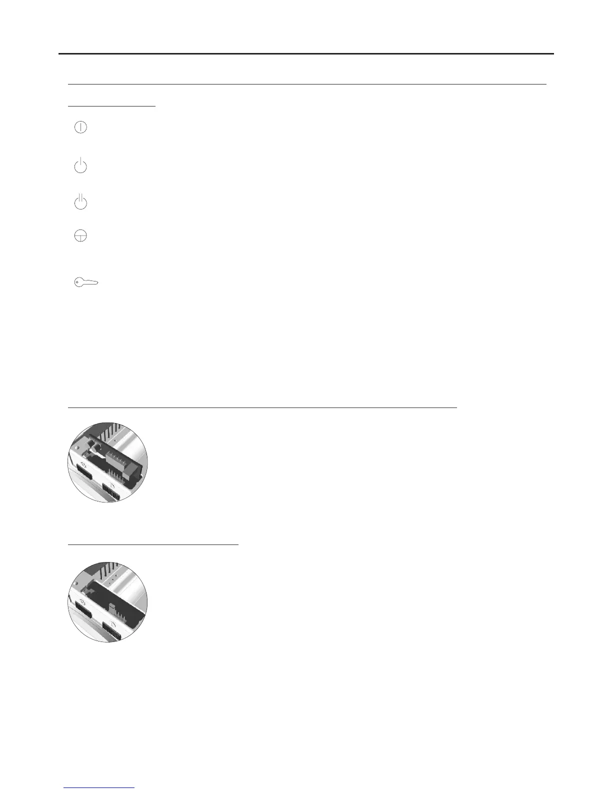
Locate the CN4 connector positioned at the bottom of the monitor. Remove the connector jumper
and insert the EL562 module.
NOTE: in this type of installation, the SW1-3 DIP switch on the sound module must be set to ON
(see p. 117). Use the specific wiring diagram.
E 562 module for video door entry system installations with twisted pair cable:L
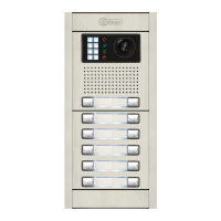
The end of line jumper is located on the CN4 connector at the bottom of the monitor.
In case of twisted pair cable installations, the end of line jumper is placed in the EL562 module,
also located in the CN4 connector of the monitor base.
Do not remove the jumper on monitors where the video cable finish. Remove the jumper on
monitors where the video cable continue.
Handling of the end of line jumper:
147
AUDIO AND VIDEO DOOR ENTRY SYSTEM - CODED PANEL WITH DISPLAY