Access control with call buttons...................................................................................................................................23.
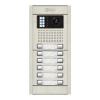
Description of the Nexa modular door panel.......................................................................................................... 25-26.
Description of the sound modules...............................................................................................................................27.
Description of the EL655 sound module...................................................................................................................27
Description of the EL651 sound module...................................................................................................................28
Description of the EL620/2PLUS sound module...................................................................................................... 29.
Description of the SW1 DIP switch........................................................................................................................30
Description of the self-testing LEDs.................................................................................................................... 30...
Description of the EL632/PLUS - EL642/PLUS sound module.................................................................................31
Description of the SW1 - SW2 DIP switch ........................................................................................................32-33
Binary coding of the SW2 DIP switch....................................................................................................................33.
Description of the CN8 Nexa Bus link connector...................................................................................................33.
Description of the CN3 function connector............................................................................................................34
Description of the EL632/R5 - EL642/R5 sound module..........................................................................................35.
Description of the SW1 DIP switch........................................................................................................................36
Description of the CN7 Nexa Bus link connector...................................................................................................36.
.............................................................................................................................. 37..
Description of the button modules
Description of the EL610Abutton module
................................................................................................................37.
Description of the EL610D button module................................................................................................................38
Description of the N3301/AL- NX3301 access control module....................................................................................39
Description of the JP1 jumper, SW1 DIP switch and self-testing LEDs..................................................................... 40..
Description of the beeps..........................................................................................................................................41
Installation of the door panel...................................................................................................................................... 41..
Location of the embedding box............................................................................................................................. ..41. .
Preparing the cable entry and fitting the embedding box..........................................................................................42.
Mounting the electronic modules.............................................................................................................................42
Fastening the frame to the embedding box..............................................................................................................43.
Cabling, connection and button configuration..........................................................................................................43
Closing the door panel.............................................................................................................................................43
Installation of the FA-PLUS and FA-PLUS/C power supply.........................................................................................44.
Installation of the lock release.................................................................................................................................... 44.
Description of door panel operation........................................................................................................................... 44..
Programming the door panel......................................................................................................................................44.
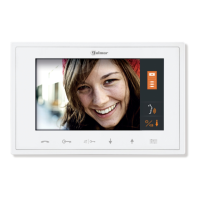
Description of the Tekna Plus monitor........................................................................................................................ 45...
Function push buttons and handling the end of line jumper...................................................................................... 46..
EL562 module for video door entry system installations with twisted pair cable........................................................46.
Description of the RCTK-PLUS wall mount connection block...................................................................................47
Installation of the monitor (monitor positioning and fixing)....................................................................................... 48..
Programming the Tekna Plus monitors.............................................................................................................. 49-50...
Description of the Tekna R5 monitor........................................................................................................................... 51..
Labelling and function push buttons........................................................................................................................ 51..
Handling the end of line jumper................................................................................................................................52
Description of the RCTK wall mount connector........................................................................................................52.
Installation of the monitor (monitor positioning and fixing)........................................................................................53.
Programming Tekna R5 monitors............................................................................................................................54.
Description of the T-540/Plus telephone.................................................................................................................. ..55. .
Description of the connection terminals and function push buttons.......................................................................... 55..
Description of the DIP switch and programming button........................................................................................... 56...
Fixing the telephone to the wall................................................................................................................................57.
Programming T-540/Plus telephones.................................................................................................................58-59
T-530/R5 ........................................................................................................................60
Description of the telephone
Description of the connection terminals and function push button
............................................................................ 60.
T-530/R5 ........................................................................................................................ 61.
Programming telephones
....................................................................................................................................................62-64.Wiring diagrams
CONTENTS
CHARACTERISTICS
Configuring access control with call buttons enables users to make calls to apartments using the call buttons and to
gain access to the building by entering a numeric code into the N3301 module.